
Permanent magnet type synchronous motor and air compressor

a synchronous motor and permanent magnet technology, applied in the direction of magnetic circuits characterised by magnetic materials, magnetic circuit shapes/forms/construction, magnetic circuit rotating parts, etc., can solve the problems of affecting and reducing the service life of permanent magnets

Inactive Publication Date: 2002-04-23
HITACHI LTD
View PDF10 Cites 25 Cited by
  • Summary
  • Abstract
  • Description
  • Claims
  • Application Information

AI Technical Summary

Benefits of technology

The magnetic flux from the permanent magnets is led to the stator through the laminated electromagnetic steel sheet and the shaft of the rotor. Further, when the permanent magnet type motor is driven by an inverter having a basic frequency of around 1 kHz, harmonic magnetic flux is induced, being caused by harmonic current from the inverter. This harmonic wave has a frequency which is 5, 7, 11, 13, 17 or 19 times as high as the basic frequency, and accordingly, harmonic loss would be caused in several components. The largest harmonic loss is induced from the shaft with no laminated electromagnetic steel sheet, which would be as high as several kW, and accordingly, a super-high speed permanent magnetic type synchronous motor is not available. However, with the provision of the laminated electromagnetic steel sheet between the shaft and the permanent magnets, as in the present invention, since the harmonic magnetic flux passes through the laminated electromagnetic steel sheet, bypassing the shaft, no shaft loss is caused, and accordingly, the loss can be decreased down to several hundreds W corresponding to iron loss of the laminated electromagnetic steel sheet.

Problems solved by technology

If the rotational speed of the motor is low, permanent magnets are directly bonded to the shaft thereof, but the permanent magnets would be fragmented and scattered if the rotational speed of the motor is high.
However, since the output power of the generator rotated at a high speed, inevitably has a high frequency, no consideration is made for a loss induced in the rotor when pulsating magnetic flux caused by high frequency current is induced in the rotor in such a case that an inverter for converting high frequency power into a power having 50 Hz or 60 Hz is added.
Further, it has been arranged in such a way that the main magnetic flux of the permanent magnets is led through the laminated electromagnetic steel sheets, and no consideration has not yet been made to such a problem that the allowable speed is restrained by the mechanical strength of the laminated electromagnetic steel sheets themselves.
The largest harmonic loss is induced from the shaft with no laminated electromagnetic steel sheet, which would be as high as several kW, and accordingly, a super-high speed permanent magnetic type synchronous motor is not available.
Further, a permanent magnet type synchronous motor having a peripheral speed of a rotor as high as several hundreds m / s, for directly driving an air compressor would cause such a disadvantage that a laminated electromagnet steel sheet provided in the rotor would be deformed by elongation due to centrifugal force.

Method used


Image

  • Permanent magnet type synchronous motor and air compressor
  • Permanent magnet type synchronous motor and air compressor
  • Permanent magnet type synchronous motor and air compressor

Examples


Embodiment Construction

Explanation will be made of the present invention in the form of preferred embodiments with reference to FIGS. 1 to 6.

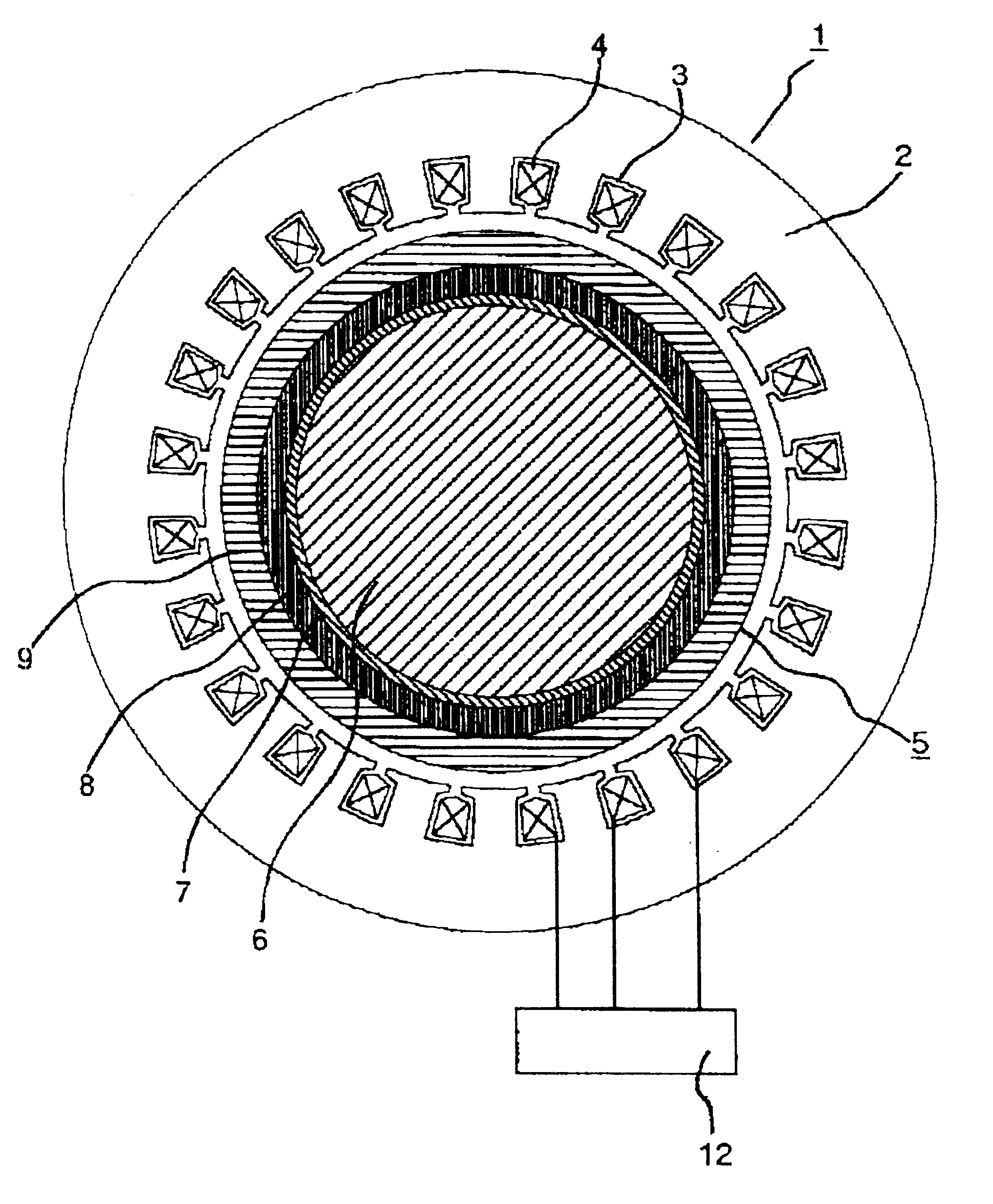
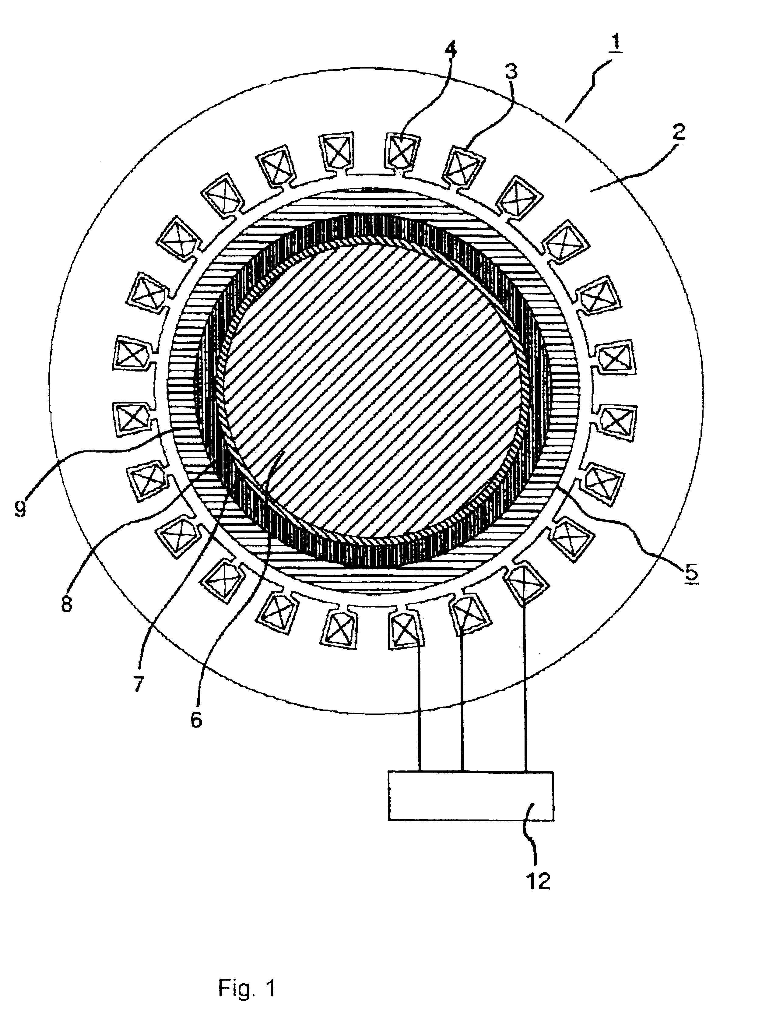
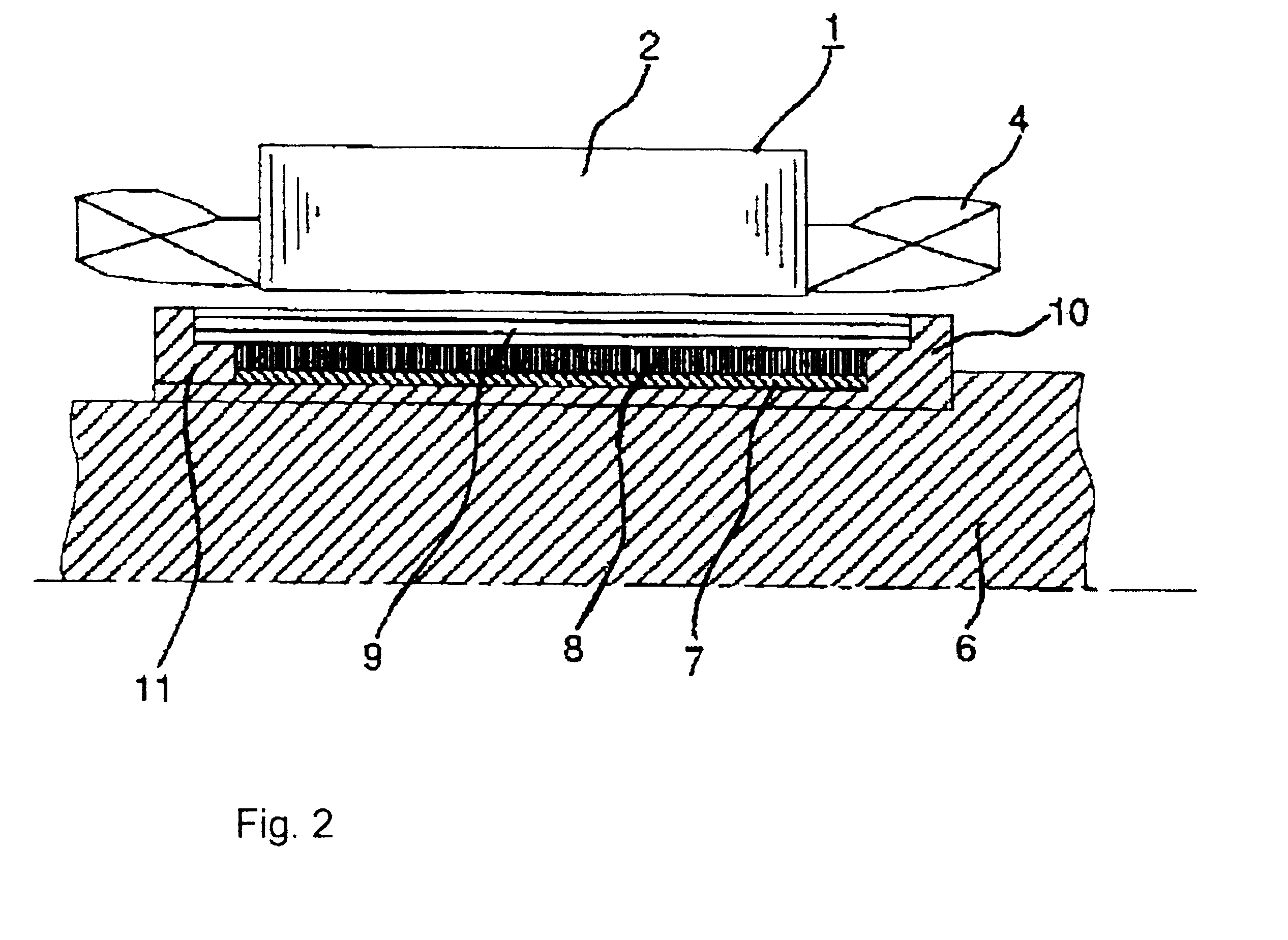
Referring to FIG. 1 which is a radially sectional view illustrating an essential part of a permanent magnet type synchronous motor in an embodiment of the present invention, and FIG. 2 which is an axially sectional view illustrating the permanent magnet type synchronous motor in the embodiment of the present invention, a stator is composed of an stationary core 2 formed therein with a plurality slots 3, and three phase u, v, w armature windings 4 wound in the slots 3.

A rotor is composed of a shaft 6 made of conductive magnetic materials, an intermediate sleeve 10 made of the same material as that of the shaft 6, and surrounding around the outer periphery of the shaft 6, a high tensile strength laminated electromagnetic steel sheet 7 surrounding around the outer periphery of the intermediate sleeve 10, a conductive permanent magnet 8 surrounding the outer periphery of...


PUM


Abstract

Provided are a super-high speed permanent magnet type synchronous motor which causes less loss in a rotor even though it is driven by an inverter adapted to be operated with a fundamental frequency around 1 kHz, and an air compressor. The air compressor having a super-high speed permanent magnet type synchronous motor which is composed of a stator in which armature windings are wound in a plurality of slots formed in a stator core, and a rotor including a shaft made of a conductive magnetic material, a conductive permanent magnet laid around the outer periphery of the shaft, and a reinforcing member made of carbon fibers and laid around the outer periphery of the permanent magnet, wherein a laminated electromagnetic steel sheet is interposed between the shaft and the permanent magnet, and the laminated electromagnetic steel sheet has a high tensile strength higher than 70 kg / mm2.

Description

1. Field of the InventionThe present invention relates to a permanent magnet type synchronous motor used as a super high-speed variable speed motor for driving a compressor or the like, and also relates to a compressor using thereof.2. Related ArtPermanent magnet type synchronous motors have been prosperously used for industrial drive sources since its motor efficiency is high. If the rotational speed of the motor is low, permanent magnets are directly bonded to the shaft thereof, but the permanent magnets would be fragmented and scattered if the rotational speed of the motor is high.As measures for eliminating the above-mentioned disadvantages, there has been provided a super-high speed permanent magnet type synchronous motor, in which carbon fibers or titanium rings are used surrounding around permanent magnets, as disclosed in Japanese Laid-Open Patent No. H10-243586 (prior art 1).Further, a rotor structure used in a high speed generator is composed of a nonmagnetic porous cylind...

Claims


Application Information

Patent Timeline
IPC IPC(8): H02K1/27H02K1/02F04B39/00H02K21/14
CPCH02K1/2733
Inventor KOHARAGI, HARUOTANIGUCHI, TSUKASAYAMAMOTO, KOUKIKIKUCHI, SATOSHITAKAHASHI, MIYOSHIMIURA, HARUOFUKUSHIMA, YASUOSENOH, MASAHARU
Owner HITACHI LTD
Learn More