Linear accelerator

a linear accelerator and accelerator technology, applied in the field of linear accelerators, can solve the problems of complex and high-precision positioning systems which are difficult to engineer in practice, devices that cannot continuously vary rf fields, and reduce the functionality of a simple switch

Inactive Publication Date: 2002-04-23
ELEKTA AB
View PDF5 Cites 30 Cited by
  • Summary
  • Abstract
  • Description
  • Claims
  • Application Information

AI Technical Summary

Problems solved by technology

There are a number of serious difficulties with this approach arising from the various other resonant parameters that are dictated by the cavity dimensions.
This demands a complex and high-precision positioning system which is difficult to engineer in practice.
In those schemes which have less than two moving parts (such as that proposed in U.S. Pat. No. 4,286,192), the device fails to maintain a constant phase between input and output, making such a device unable to vary RF fields continuously, and are thus reduced to the functionality of a simpl...

Method used


Image

  • Linear accelerator
  • Linear accelerator
  • Linear accelerator

Examples


first embodiment

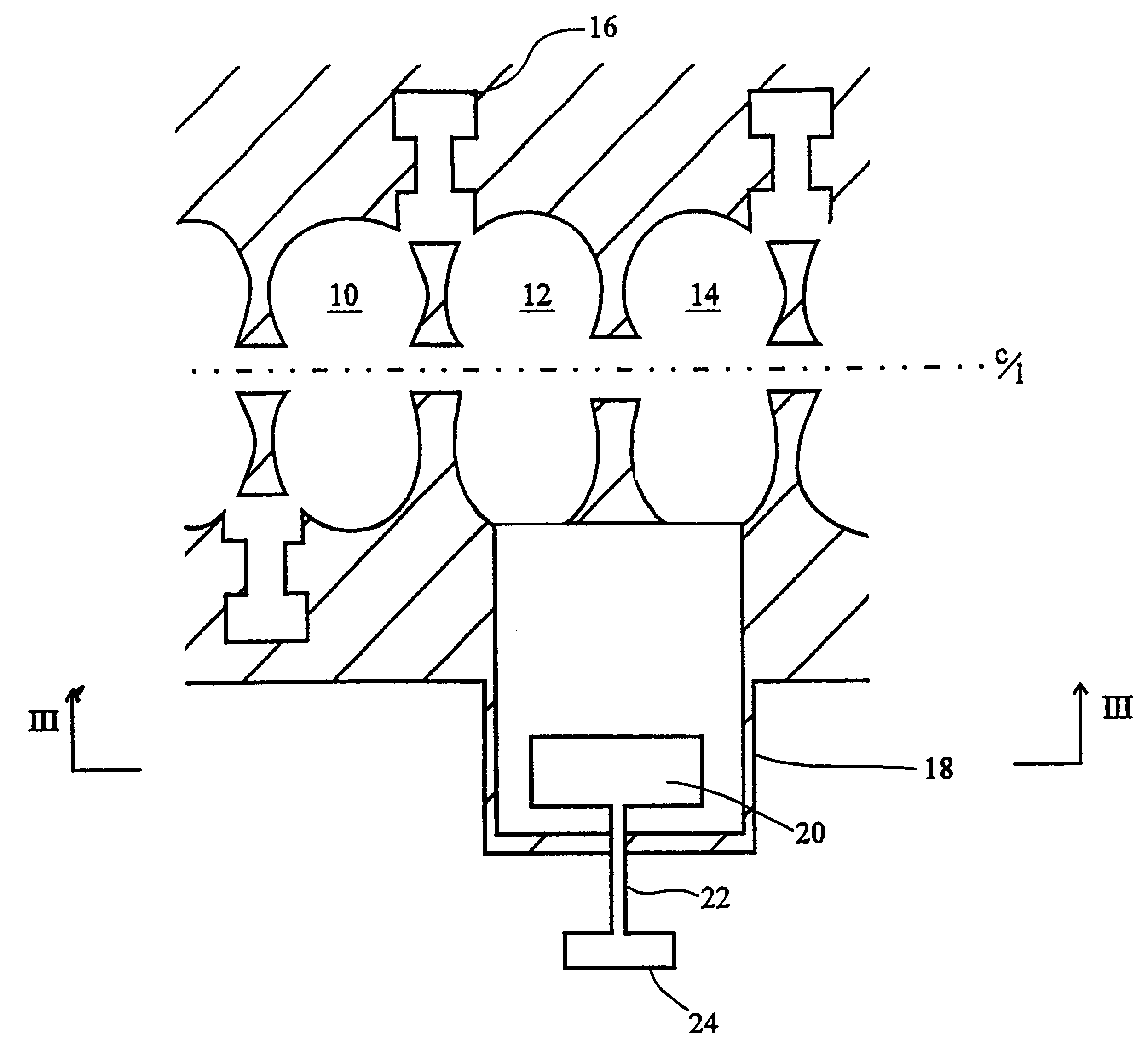
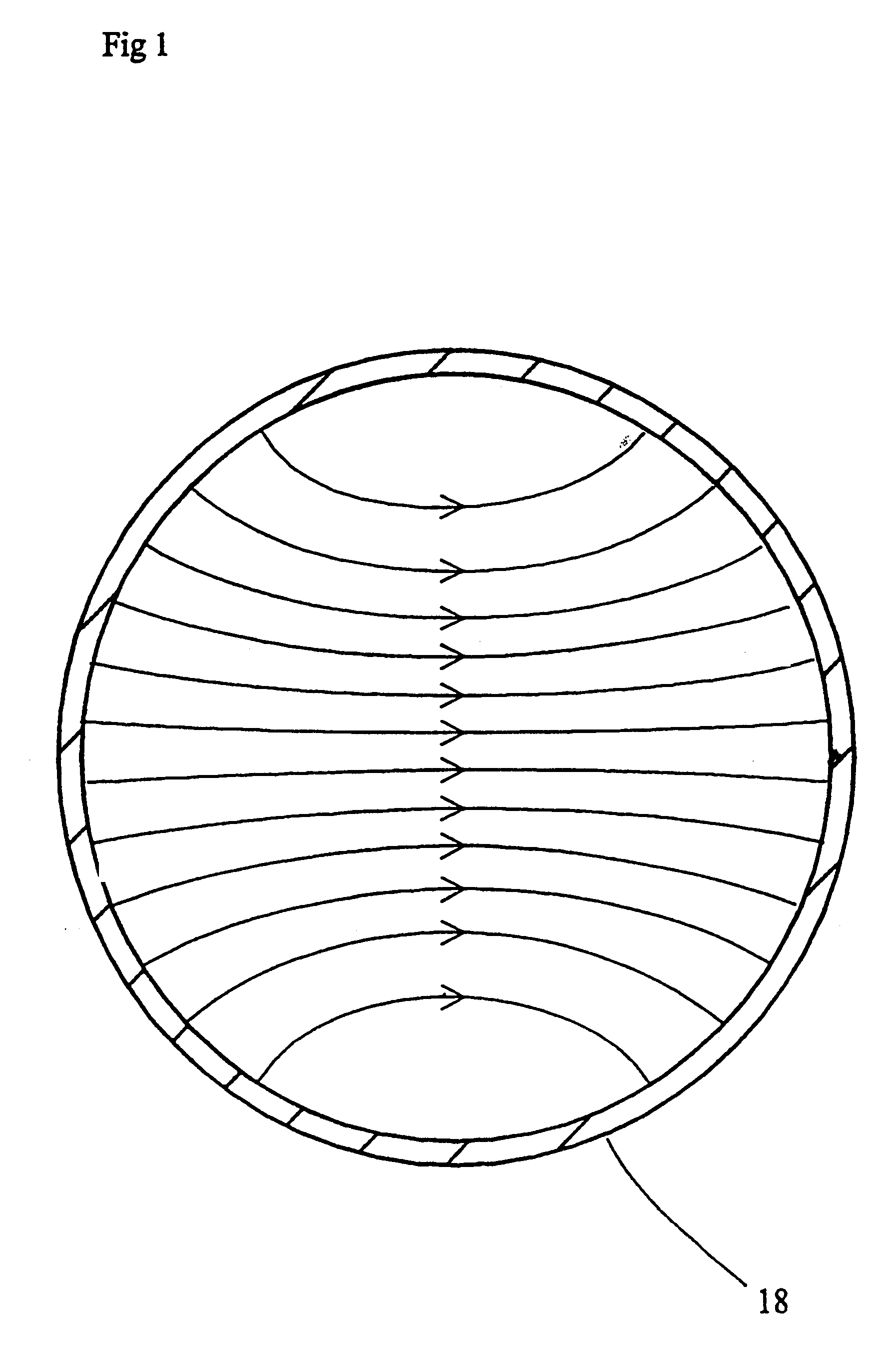
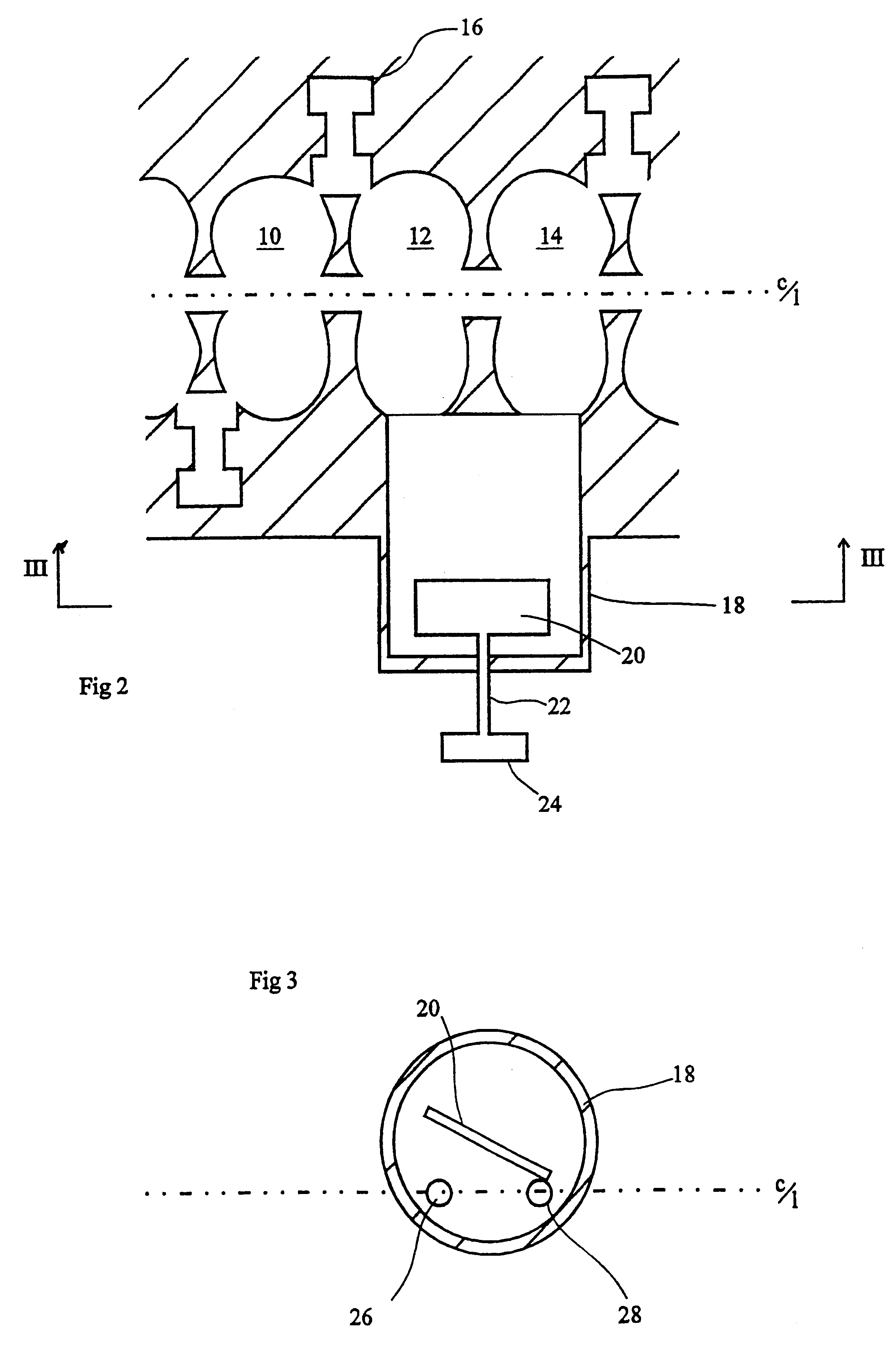
In a standing wave accelerator the device could be implemented as shown in the first embodiment, FIGS. 2 and 3. These show three on-axis accelerating cells 10, 12, 14 as part of a longer chain of cavities. The first and second accelerating cavities 10, 12 are coupled together with a fixed geometry coupling cell 16, which is known art. Between the second and third on-axis cavities 12, 14, the fixed geometry cell is replaced by a cell 18 according to the present invention. This cell 18 is formed by the intersection of a cylinder with the tops of the arches that make up the accelerating cells thus forming two odd shaped coupling holes 26, 28. To function as intended, these holes should ideally be along a (non-diametrical) chord of the off-axis cylinder, which implies that the center line of the cylinder is offset from the center line of the accelerator, as shown in the FIG. 3. These coupling holes are in region of the cavity where magnetic field dominates, and so the coupling between c...

second embodiment

shown in FIGS. 4 and 5, the coupling cavity 30 is still transverse to the longitudinal axis of the accelerating cavities, but intersects with accelerating cavities 12, 14 along a cylindrical face thereof. Thus, the axes of the accelerator and of the coupling cavity do not intersect, but extend in directions which are mutually transverse. The paddle 20 etc. is unchanged. Otherwise, the operation of this embodiment is the same as the first.

third embodiment

FIGS. 6-10 illustrate the present invention. In the Figures, a short sub-element of a linear accelerator is illustrated, consisting of two accelerating cavities and the halves of two coupling cavities either side. In addition, the element includes a single coupling cavity embodying the present invention, joining the two accelerating cavities. A complete accelerator would be made up of several such sub-elements joined axially.

In FIG. 6, the axis 100 of the accelerating cavities passes into a small opening 102 into a first coupling cavity 104 (not visible in FIG. 6). A further accelerating cavity 108 communicates with the first accelerating cavity 104 via an aperture 106. The second cavity 108 then has a further aperture 110 on its opposing side to communicate with subsequent accelerating cavities formed when the sub-element of this embodiment is repeated along the axis 100. Thus, a beam being accelerated passes in order through apertures 102, 106, 110 etc.

A pair of coupling half-cavi...


PUM


Abstract

This device allows the variation of the coupling between two points in an RF circuit in a very simple way while maintaining the RF phase relationship and varying the relative magnitude of the RF fields. The device is characterized by a simple mechanical control of coupling value, that has negligible effect on the phase shift across the device. This is achieved by the simple rotation of the polarisation of a TE111 mode inside a cylindrical cavity. Such a device does not contain resistive elements, and the sliding mechanical surfaces are free from high RF currents. This device finds an application in standing wave linear accelerators, where it is desirable to vary the relative RF field in one set of cavities with respect to another, in order that the accelerator can operate successfully over a wide range of energies.

Description

BACKGROUND FIELD OF THE INVENTIONThe present invention relates to a linear accelerator.Linear accelerators, particularly of the standing wave design, are known as a source of an electron beam, for example for use in X-Ray generation. This beam can be directed to an X-ray target which then produces suitable radiation. A common use for such X-rays or for the electron beam is in the medical treatment of cancers etc.It is often necessary to vary the incident energy of the electron beam on the X-ray target. This is particularly the case in medical applications where a particular energy may be called for by the treatment profile. Linear standing wave accelerators comprise a series of accelerating cavities which are coupled by way of coupling cavities which communicate with an adjacent pair of accelerating cavities. According to U.S. Pat. No. 4,382,208, the energy of the electron beam is varied by adjusting the extent of rf coupling between adjacent accelerating cavities. This is normally ...

Claims


Application Information

Patent Timeline
IPC IPC(8): H05H7/18H05H7/14H05H9/00H05H9/04
CPCH05H9/04H05H7/18
Inventor ALLEN, JOHNBRUNDLE, LEONARD KNOWLESLARGE, TERRY ARTHURBATES, TERENCE
Owner ELEKTA AB
Why Eureka
Try Eureka