
Ball actuator

a technology of actuators and balls, applied in the direction of magnets, magnets, cores/yokes, etc., can solve the problems of radial forces transmitted to the rod, extreme sensitive to dimensional tolerances and wear of parts, and the latched position cannot be fully transmitted to the second ball

Inactive Publication Date: 2002-04-23
SCHNEIDER ELECTRIC IND SAS
View PDF9 Cites 26 Cited by
  • Summary
  • Abstract
  • Description
  • Claims
  • Application Information

AI Technical Summary

Benefits of technology

Another object is to reduce the dimensions of the actuator for a given stored mechanical energy. Another object is to increase the travel of the movable means delivering the stored kinetic energy. Another object is to make the actuator mechanism relatively insensitive to dimensional variations due to manufacturing tolerances or wear. Another object is to make the actuator relatively insensitive to mechanical impacts and vibrations. Another object is to increase the speed of the actuator. In a more general manner, another object is finally to reduce the manufacturing cost of the actuator.
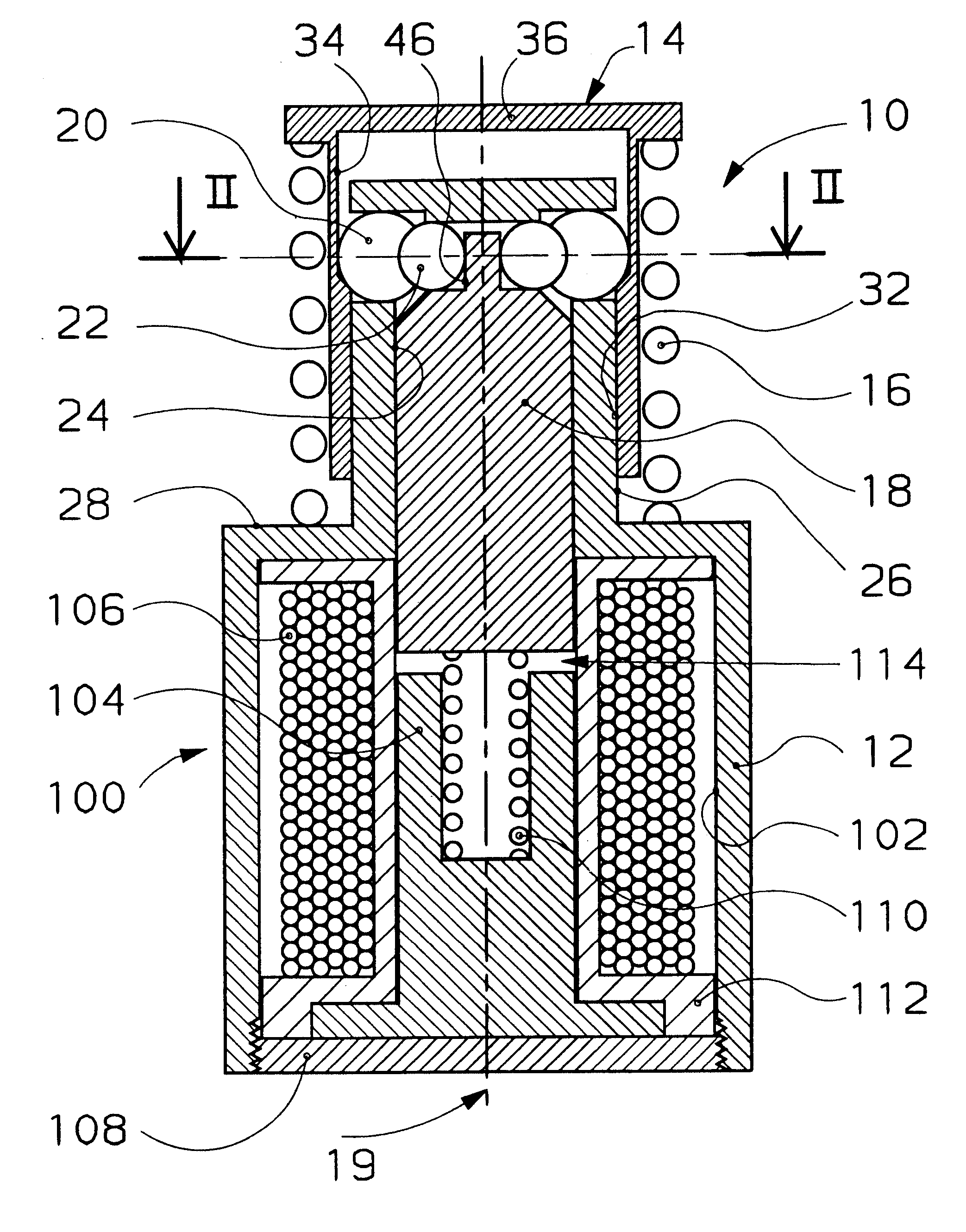
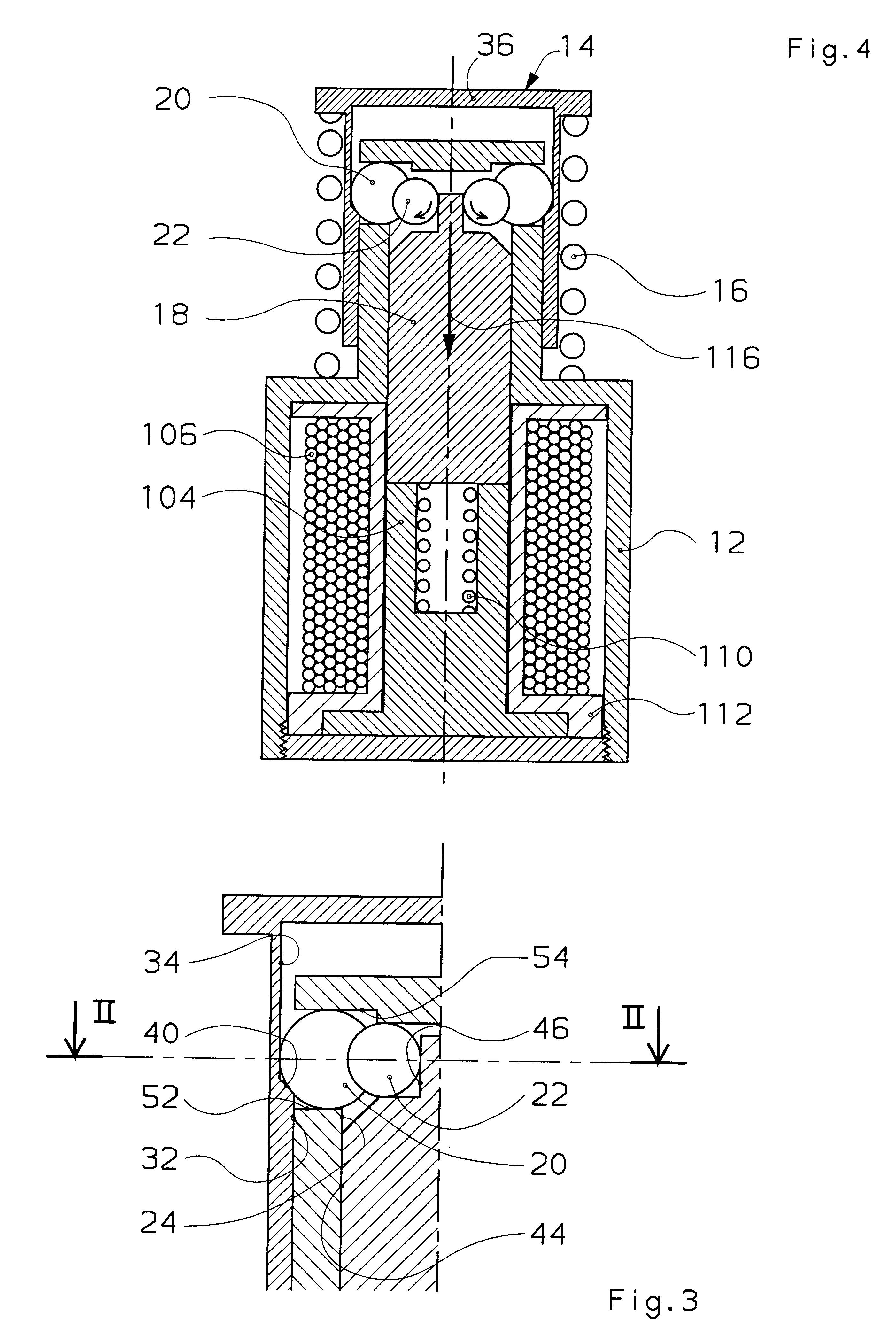
Advantageously, the control balls, the detent balls and at least a part of the rod are housed in a cavity confined by walls of the case and by the striker, said walls forming a guiding surface operating in conjunction with the striker so as to achieve dust-tightness when the striker moves between the loaded position and the unloaded position. Reliability of the mechanism is thus achieved with a great saving of means.

Problems solved by technology

Such a device has a relatively good performance, but it is extremely sensitive to dimensional tolerances and to wear of the parts.
Moreover, if the diameter of the second ball does not correspond exactly to the distance between the rod and the case, the radial forces transmitted to the rod by the first ball in the latched position will not be fully transmitted to the second ball and will tend to deform the rod.
As soon as the device is subjected to impacts or vibrations tending to de-align the rollers, the return springs are subjected to strong stresses due to the forces exerted by the bolt.
The travel of the bolt is moreover limited.
The operating energy required for movement of the rod between its latched control position and its unlatched control position is therefore low.
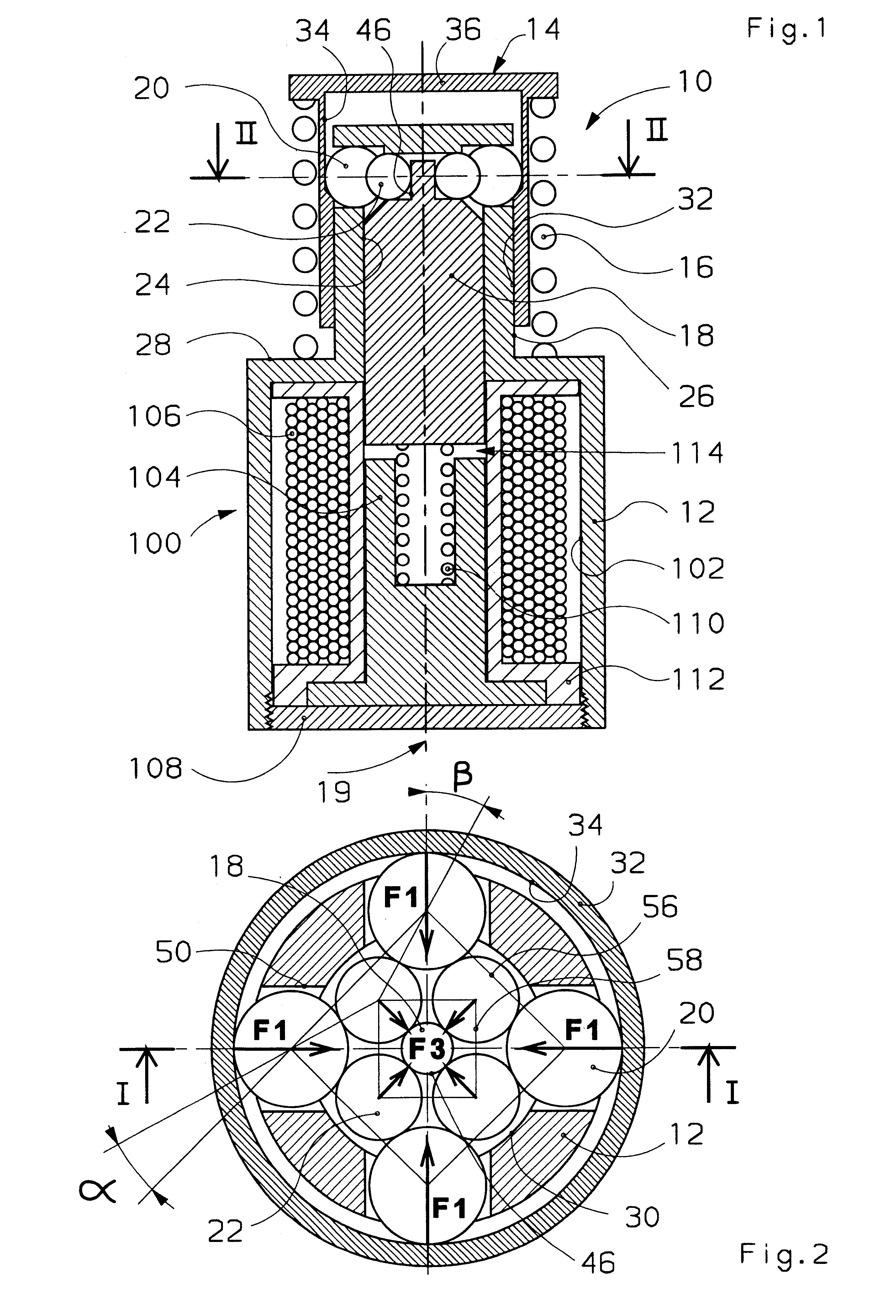
The control balls are thus automatically centered by the combined action of the detent balls, which makes the device relatively insensitive to the effects of dimensional dispersions and wear.
Furthermore, the assembly obtained is particularly compact.
The tripping movement is then very fast, and the power required to move the rod to the unlatched position is very low.

Method used


Image

  • Ball actuator
  • Ball actuator
  • Ball actuator

Examples


first embodiment

It can therefore be seen that the ratio F.sub.3 / F.sub.1 is always less than 1. In the particular case considered in the invention, where n=4, we obtain: ##EQU5##

The modulus F.sub.3 of the force exerted by the control balls on the rod in the loaded position conditions the energy required for operation of the rod. By making the diameter of the rod and the diameter of the balls vary, we can make the angle .beta. in the gap, and therefore the value of F.sub.3 for a given latching force F.sub.1, vary. A wide range of actuators can therefore be obtained using more or less powerful springs without having to vary the operating energy.

The theoretical limit of the model is obtained with the purely theoretical diagram of FIG. 7 where the angle .alpha. is zero and where the force F.sub.3 transmitted to the rod 18 is nil.

The above simplified model does not take account of the dimensional differences due to the tolerances and wear of the mechanism. It should however be underlined that the contro...

second embodiment

According to a variant, not represented, of the second embodiment, it is also possible to provide a device wherein the plane containing the centers of the control balls is situated below the plane containing the centers of the detent balls, so that the control balls exert on an intermediate stop of the rod a force having an axial component tending to repel the rod against an end of travel stop. Such an actuator has a stable loaded position. To release the energy storage spring, the rod has to be driven upwards so that the control balls repel the detent balls radially towards the outside, which detent balls, in contact with a ramp of the shoulder, repel the striker axially against the force exerted by the energy storage spring. As soon as the control balls pass the dead point and are situated above the detent balls, the control balls are ejected as in the previous embodiments and the striker is released. This embodiment naturally procures the advantage of a greater stability in the l...


PUM

PropertyMeasurementUnit
radial forcesaaaaaaaaaa
forcesaaaaaaaaaa
diameteraaaaaaaaaa

Abstract

A ball actuator 10 comprises a case 12 supporting a striker 14 with an energy storage spring 16, a control rod 18 movable in translation in a direction parallel to a geometric axis 19, detent balls 20 and control balls 22. When the rod is moved in translation by an electromagnetic relay 100, the control balls 22 escape and enable the detent balls 20 to be freed so that the striker 14 is released. Each control ball 22 is in contact with two detent balls 20 and with the rod 18 so that the forces applied to the rod 18 by the control balls 20 are much lower than the forces exerted by the striker 14 on the detent balls 22. A high-efficiency actuator is thus achieved requiring a low operating energy and with small overall dimensions.

Description

The invention relates to a ball actuator of great efficiency and with small dimensions, designed in particular for commanding an opening and closing mechanism of an electrical switchgear apparatus, in particular for command of a power circuit breaker.STATE OF THE ARTThe document DE 2,340,450 describes a latching device with detent balls for latching an electrical switch, comprising a latching bolt sliding in translation in a case and a control sub-assembly formed by a control rod with axial movement arranged perpendicularly to the axis of translation of the bolt and equipped with a support plate for two balls. In the latched position, a first of the two balls bears on one side on a flat end of the bolt and on the other side on the rod. The surface of the flat end of the bolt is parallel to the contact surface of the rod so that the bolt only transmits purely radial forces to the rod. These forces are taken up by the second ball located between the rod and the case. The end of the bo...

Claims


Application Information

Patent Timeline
Patent Type & Authority Patents(United States)
IPC IPC(8): H01H71/10H01H71/50H01H71/12H01H71/24H01F7/16H01F7/121H01H73/36
CPCH01H71/505H01H71/2463H01H2071/506
Inventor BATTEUX, PIERRE
Owner SCHNEIDER ELECTRIC IND SAS
Learn More