Braking force control device

a technology of braking force and control device, which is applied in the direction of braking system, process and machine control, instruments, etc., can solve the problems of inability to accurately calculate difficulty in accurately calculating vehicle acceleration or wheel acceleration, and inability to accurately know the frictional force characteristic of tire road surface, etc., to achieve the effect of improving control stability

Inactive Publication Date: 2002-04-23
TOYOTA JIDOSHA KK +2
View PDF15 Cites 26 Cited by
  • Summary
  • Abstract
  • Description
  • Claims
  • Application Information

AI Technical Summary

Benefits of technology

The present invention is proposed in order to overcome the above-described drawbacks, and an object of the present invention is to provide a braking force control device which correctly grasps the road surface state and can carry out optimal control which is appropriate for the road surface state. Further, an object of the present invention is to provide a braking force control device which can improve control stability at the time of limit braking during turning.
In accordance with the fourth aspect, the lateral slip information detecting means detects lateral slip information of the wheel. This lateral slip information of the wheel may be, for example, the direction of generation force of the wheel or the slip angle. Further, the direction of tire generation force substantially corresponds to the steering angle of the steering wheel of the vehicle. Thus, the lateral slip information detecting means may detect the steering angle of the steering wheel of the vehicle. In this case, a steering angle sensor may be used as the lateral slip information detecting means. The control means controls the braking force of the wheel for each wheel on the basis of the estimated road surface .mu. slope and the lateral slip information. In this way, by controlling the braking forces of the respective wheels in consideration of the lateral slip information, even in a case in which there is lateral slip, the total slip region can be prevented from being reached, and the control stability at the time of braking while turning can be improved.

Problems solved by technology

Accordingly, a problem arises in that this threshold value is not always the optimal value of a given tire for a given road surface.
Thus, it is difficult to accurately compute the vehicle acceleration or the wheel acceleration.
As a result, a problem arises in that the tire frictional force characteristic with respect to tire road surface cannot be accurately known.
Further, in conventional methods, it cannot be judged what type of conditions there are at the .mu.-S characteristic at the time of ABS control.
As a result, it is extremely difficult to judge whether pressure should be increased immediately or whether pressure should be increased slowly.
However, in a case in which a slip angle arises, i.e., in a case in which lateral slip arises at the wheel due to braking while turning, when follow-up control is effected such that the braking force slope becomes a target value in a vicinity of zero, a problem arises in that there is the possibility that the limit of the tire generation force characteristic will be exceeded.

Method used


Image

  • Braking force control device
  • Braking force control device
  • Braking force control device

Examples


first embodiment

(First Embodiment)

The present invention can be applied to, for example, an ABS control device 1 having the structure illustrated in FIG. 4. The ABS control device 1 includes wheel speed sensors 10 (10FL, 10FR, 10RL, 10RR) which detect the wheel speeds of the respective wheels; a stop switch 11 which detects that the brake pedal has been depressed; an electronic control unit (hereinafter, "ECU") 20 which controls the entire device; and an ABS fluid pressure circuit 40 which carries out brake control in accordance with control of the ECU 20.

The ECU 20 includes amplifiers 21 (21FL, 21FR, 21RL, 21RR) which amplify signals from the wheel speed sensors 10; an amplifier 22 which amplifies a signal from the stop switch 11; an input port 23 which converts an inputted signal into a signal which can be processed internally; a CPU 24 which carries out a predetermined computation processing; an ROM 25 which stores a control program and the like; a RAM 26 in which signals are temporarily stored; ...

second embodiment

(Second Embodiment)

Next, a second embodiment of the present invention will be described. Circuits, processings and the like which are the same as those of the first embodiment are designated by the same reference numerals, and detailed description thereof is omitted.

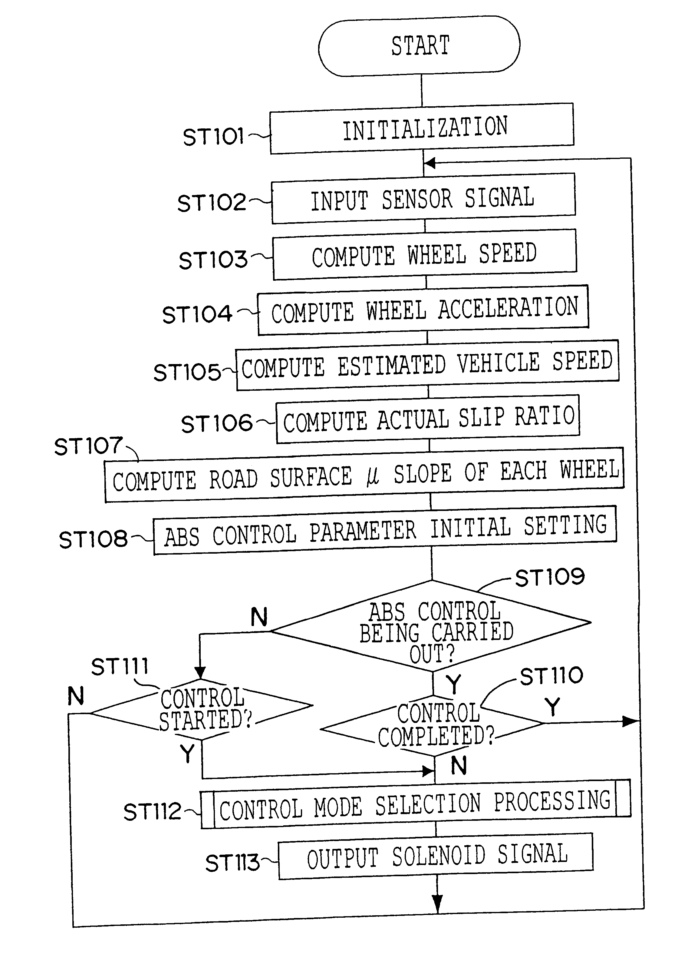
In the present second embodiment, as shown in FIG. 23, the ABS control device 1 carries out .mu. split / turning judgement processing (step ST20) between step ST7 and step ST8. Here, specifically, the subroutine processings from step ST91 through step ST95 shown in FIG. 24 are carried out. Note that these processings may be carried out while ABS control is carried out, or while ABS control is not being carried out.

The correction circuit 63 of the ABS control device 1 judges whether a road surface .mu. slope KR of a right wheel, which is estimated by the road surface .mu. slope estimating circuit 62, is greater than or equal to a predetermined value K18 (KR.gtoreq.K18), or whether a road surface .mu. slope KL of a left whee...

third embodiment

(Third Embodiment)

Next, a third embodiment of the present invention will be described. Circuits and processings which are the same as those of the previously-described embodiments are denoted by the same reference numerals, and detailed description of these same circuits and processings will be omitted.

The ABS control device 1 relating to the present third embodiment has the structure illustrated functionally in FIG. 28. Namely, the ABS control device 1 includes wheel speed sensors 10 which detect vehicle wheel speeds; a wheel acceleration detecting circuit 81 which detects the wheel acceleration of each wheel on the basis of the wheel speeds from the wheel speed sensors 10; a road surface .mu. slope estimating circuit 62 which estimates a road surface .mu. slope on the basis of the wheel speeds; a mode control circuit 82 which carries out selection control of the operation mode on the basis of the wheel accelerations or the road surface .mu. slopes or the like; and an ABS fluid pre...


PUM


Abstract

A braking force control device is provided in which wheel speeds of respective wheels of a vehicle are detected. On the basis of detected wheel speeds, a road surface .mu. slope, which is a slope of a coefficient of friction .mu. between a wheel and a road surface, is estimated for each wheel. On the basis of the road surface .mu. slope estimated for each wheel, a braking force of each wheel is controlled such that the braking force of each wheel is adjusted.

Description

BACKGROUND OF THE INVENTION1. Field of the InventionThe present invention relates to a braking force control device, and in particular, to a braking force control device which controls the braking force applied to a wheel on the basis of the road surface .mu.slope or a physical value equivalent thereto.2. Description of the Related ArtConventionally, antilock brake (ABS) control devices as follows have been proposed. Time series data of wheel speed is detected each time a predetermined sampling cycle occurs. On the basis of the detected time series data of the wheel speed, the history of changes of the wheel speed and the history of changes of the wheel acceleration are computed. On the basis of these computed values, a braking force slope (the slope of the braking force with respect to the slip speed) is estimated. The braking force applied to the wheel is controlled on the basis of the estimated braking force slope.Braking force of a tire is generated by the slip between the tire ...

Claims


Application Information

Patent Timeline
Patent Type & Authority Patents(United States)
IPC IPC(8): B60T8/1763B60T8/172B60T8/17B60T8/84
CPCB60T8/172B60T8/17636B60T2210/12
Inventor YASUI, YOSHIYUKIASANO, KENJIITO, SHOJITANAKA, AKIRAYOSHIDA, HIROAKISAWADA, MAMORUMURAGISHI, YUJIISHIGURO, MICHIOMATSUNAGA, TSUGIHARUONO, EIICHI
Owner TOYOTA JIDOSHA KK
Why Eureka
Try Eureka