Method for controlling air speed in a sterilizing tunnel during the heating of same tunnel

Inactive Publication Date: 2002-05-07
ROBERT BOSCH GMBH
View PDF3 Cites 26 Cited by
  • Summary
  • Abstract
  • Description
  • Claims
  • Application Information

AI Technical Summary

Benefits of technology

The method of the invention for controlling the air speed in a sterilizing tunnel during its heating phase, has the advantage over the prior art that it works without additional air speed measuring instruments and at the same time is sufficiently precise, and the filter elements always function optimally. It follows from this that the fan or the filters need not be made more powerful, and th

Problems solved by technology

A disadvantage of this known method is that the air speed measuring instruments, because of the high temperatures attained in the sterilizing tunnel, such as 350.degree. C. at the end of the heating phase, have only a brief dwell time.
Furthermore, because of the additional measuring instruments and control units, the known sterilizing tunnels are complicated in design.
Measurement errors, for instance from soiling of the measuring devices, also go undetected, so that the sterilization

Method used


Image

  • Method for controlling air speed in a sterilizing tunnel during the heating of same tunnel
  • Method for controlling air speed in a sterilizing tunnel during the heating of same tunnel

Examples


Embodiment Construction

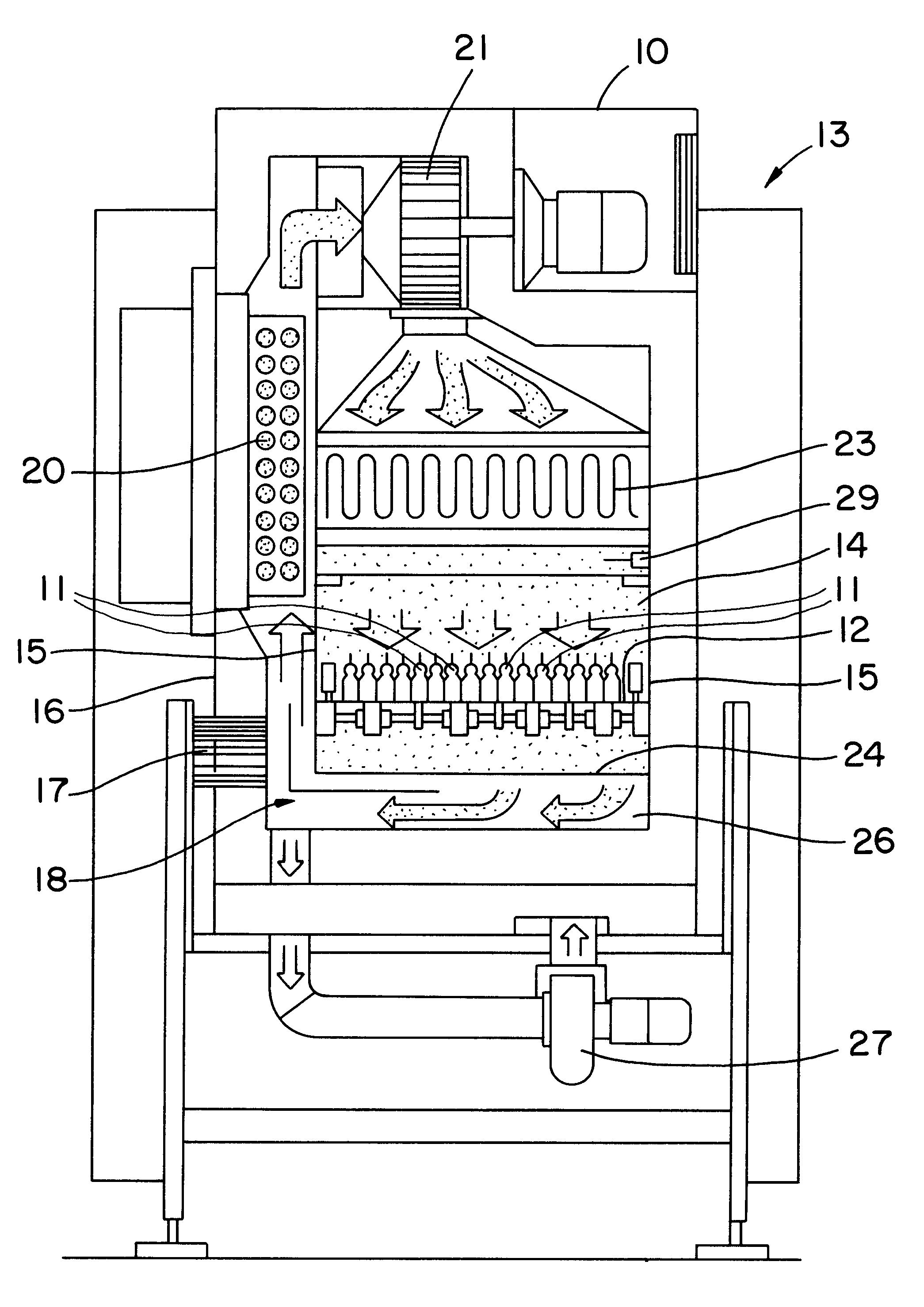
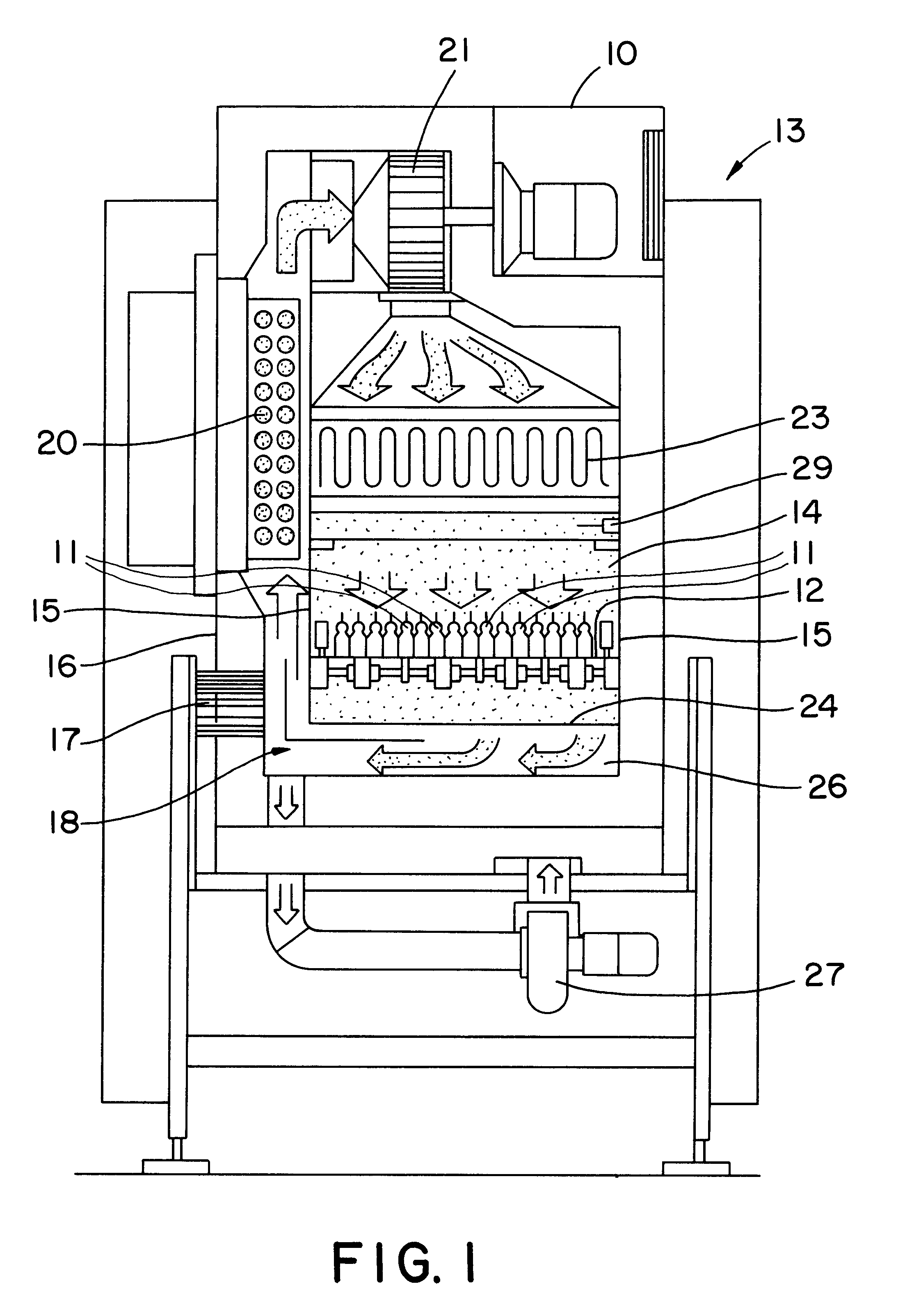
The sterilizing tunnel 10 shown in FIG. 1 is used to handle pharmaceutical containers 11, such as ampules vials or the like, before they are filled. This requires that the containers 11, furnished in nonsterile condition, be sterilized. This is done in the sterilizing tunnel 10 by introducing the containers 11, wet-cleaned beforehand, into the sterilizing tunnel 10, in which, by means of a horizontally revolving, continuously driven conveyor belt 12, the containers are preheated first, in an inlet region not shown, from room temperature to approximately 40.degree. C. Next, the containers 11 pass into the region of the hot area 13 shown in FIG. 1, in which the containers 11 are further heated to approximately 350.degree. C.; germs and the like are killed by the heating and a hot air flow. Finally, the containers 11 are cooled down to room temperature again in a cooling area, also not shown, from which the containers are carried on to a filling system.

In the heating area 13, the steri...


PUM

PropertyMeasurementUnit
Temperatureaaaaaaaaaa
Timeaaaaaaaaaa
Speedaaaaaaaaaa

Abstract

In a tunnel-like region of a sterilizing tunnel, containers are advanced by means of a conveyor device. For sterilization, a heated air flow oriented vertically in the region of the containers is used, which is generated by means of a fan and a heater. To prevent particles from being torn out of a sterile filter during the heating phase, there is a provision for adapting the rpm of the fan during the heating phase. According to the invention, this rpm adaptation is done by ascertaining the requisite rotary speeds of the fan beforehand at both room temperature and the sterilization temperature, whereupon a control unit of the sterilizing tunnel, on the basis of a predetermined functional relationship, raises the rpm of the fan as the temperature of the air flow is raised.

Description

PRIOR ARTThe invention is based on a method for controlling the air speed in a sterilizing tunnel during its heating phase. Such sterilizing tunnels are used particularly to sterilize ampules, vials or the like in the pharmaceutical packaging industry. Filter elements for cleaning the air recirculated in the sterilizing tunnel are disposed in the sterilizing tunnels. So that the filter elements will on the one hand not be damaged but on the other hand will have their optimal cleaning effect and so that no particles will be torn out of the filter elements, it is necessary that the flow through the filter elements be at a certain air speed.In a known method of this type, to attain a virtually constant air speed at various temperatures in the sterilizing tunnel during its heating phase, speed measuring instruments are used, which are coupled via a control unit to a fan, whose rpm is varied in accordance with the measured air speed. A disadvantage of this known method is that the air sp...

Claims


Application Information

Patent Timeline
IPC IPC(8): B65B55/04B65B55/02B65B55/10B65B55/06
CPCB65B55/10B65B55/025
Inventor PENNEKAMP, INGBERTHILLEBRAND, KLAUS
Owner ROBERT BOSCH GMBH
Why Eureka
Try Eureka