Solder reflow oven

a reflow oven and oven technology, applied in the direction of soldering equipment, furnaces, lighting and heating equipment, etc., can solve the problems of not being able to achieve the effect of reflowing, and being difficult to achiev

Inactive Publication Date: 2002-05-14
ASM ASSEMBLY AUTOMATION LTD
View PDF12 Cites 53 Cited by
  • Summary
  • Abstract
  • Description
  • Claims
  • Application Information

AI Technical Summary

Problems solved by technology

However, PCB reflow is a more complex operation that requires as a result an oven that is larger, more complex and more expensive than might be necessary for solder ball reflow alone.
Furtherm

Method used


Image

  • Solder reflow oven
  • Solder reflow oven
  • Solder reflow oven

Examples


Embodiment Construction

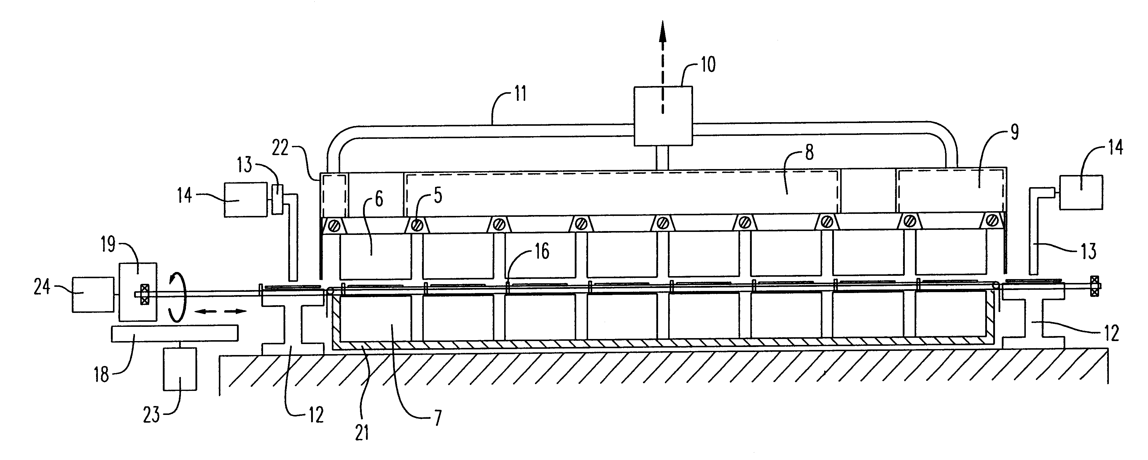
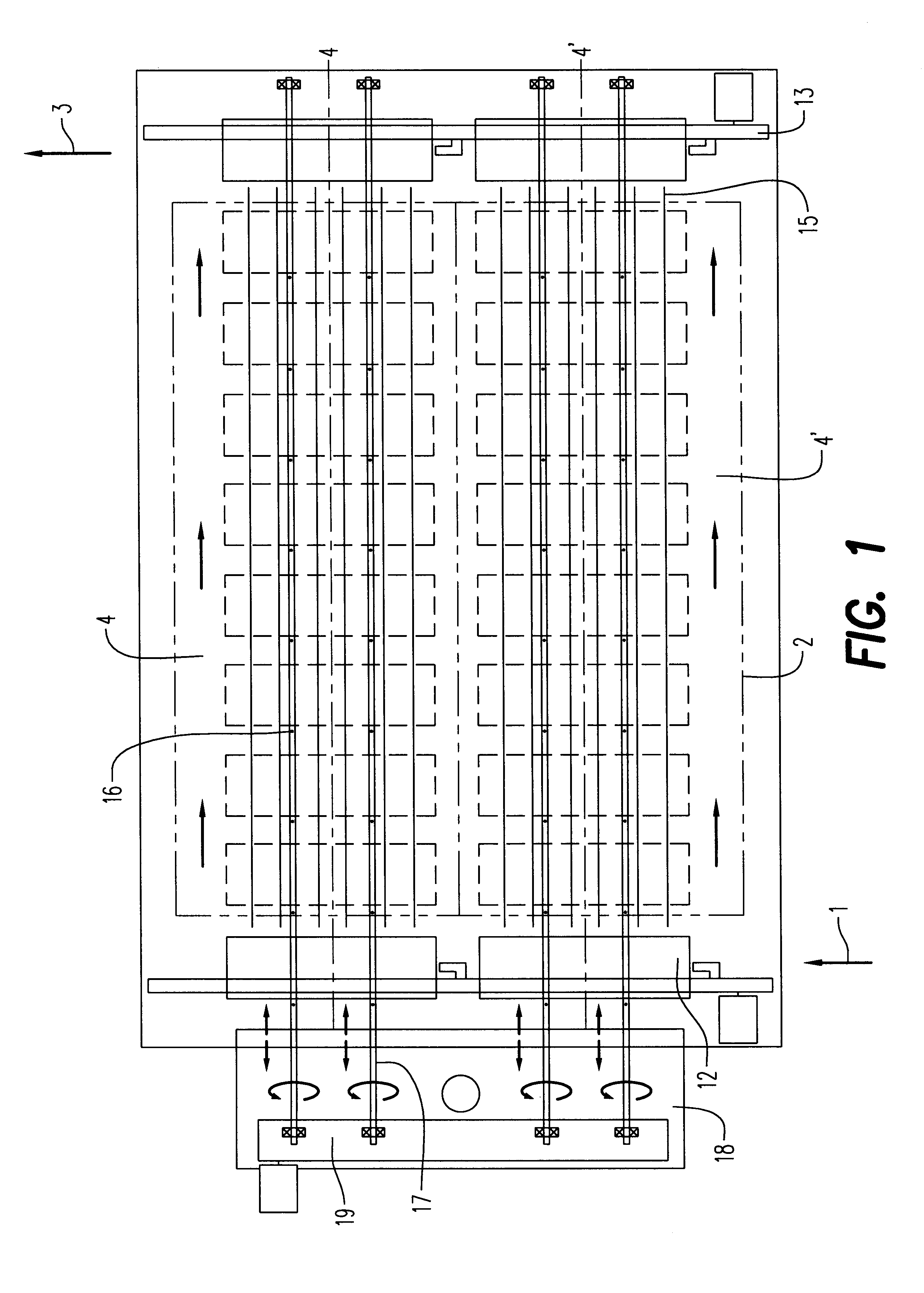
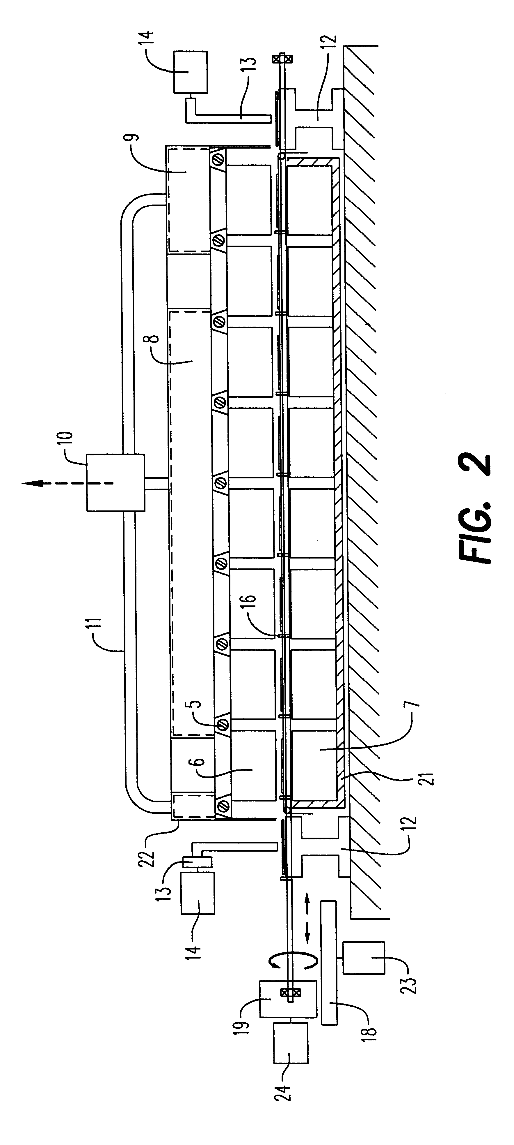
FIGS. 1 and 2 show the overall structure of a solder reflow oven in accordance with an embodiment of the present invention. The oven comprises an input station 1, a process chamber 2, and an output station 3. BGA substrates on which solder balls have been placed enter the oven through the input station 1, are subject to the reflow process within process chamber 2, and are output from the oven after reflow is complete through output 3. In this specification the term "process direction" means the direction of travel of the substrates through the process chamber towards the output station. It should be noted from FIG. 1 that in this embodiment of the invention, the oven comprises two parallel tunnels 4,4' that allow reflow of two sets of substrates to be carried out simultaneously. However, the number of tunnels is not limited to two, and in fact it can be more than two when higher throughput is necessary. Each tunnel 4,4' within the process chamber 2 is divided into a number of heatin...


PUM

PropertyMeasurementUnit
Angleaaaaaaaaaa
Distanceaaaaaaaaaa
Partition functionaaaaaaaaaa

Abstract

A solder reflow oven for the processing of ball grid array substrates bearing solder balls is described, comprising: input means for introducing substrates into the oven, a processing chamber within which the substrates are subject to a solder reflow process, and output means for discharging substrates from the oven for further processing or handling, and means for transferring the substrates through the processing chamber in a first direction towards the output means. The processing chamber comprises a plurality of heating and cooling zones arranged with a constant pitch in the first direction, and the transferring means is adapted to move the substrates in the first direction in stages, with each component moving a distance equal to the pitch between two zones in each stage, whereby the components are moved from zone to zone in stages. In addition each block of each heating zone and each block of each cooling zone is connected to a source of fresh gas, and each block of each heating zone is provided with means for heating the gas, and each block of each cooling zone is provided with means for cooling the gas, and each block is formed with a serpentine channel between the source of fresh gas and at least one opening through which the gas is discharged from the block towards a substrate.

Description

This invention relates to a solder reflow oven, and in particular to such an oven suitable for reflowing solder balls placed on solder pads of a ball grid array (BGA) substrate. The invention also relates to a compact and advantageous system for solder ball attachment in BGA electronic packages.A ball grid array (BGA) is a well-known and increasingly popular form of electronic package design for the use in the manufacture of integrated circuits. One of the important steps in the manufacturing process for a BGA is the firm attachment of solder balls onto solder pads formed on a BGA substrate. The solder ball is used to maintain electrical connectivity between the BGA substrate and any components attached thereto. The attachment of the solder balls to the solder pads involves two main steps: (1) solder ball placement, and (2) solder reflow. The first step involves the picking of a number of solder balls from a supply means by a pick head, and then the placement of those balls in a des...

Claims


Application Information

Patent Timeline
IPC IPC(8): B23K1/008H01L21/60B23K3/00
CPCB23K1/008B23K2201/40B23K2101/40B23K3/00H01L21/60
Inventor CHENG, CHI WAHCHONG, PING CHUN BENSONTANG, HOI SHUEN JOSEPHWU, KAI CHIU ADAMYUE, KA ON ALFRED
Owner ASM ASSEMBLY AUTOMATION LTD
Why Eureka
Try Eureka