Component assembling method and component assembling apparatus

a technology of component assembling and assembly method, which is applied in the direction of manufacturing tools, transportation and packaging, rigid containers, etc., can solve the problems of increasing the installation cost, increasing the number of assembling steps and reducing the overall cost of the assembling process. , the structure of the assembling apparatus is simplified, and the overall cost of the assembling process is reduced.

Inactive Publication Date: 2002-05-21
PANASONIC CORP
View PDF25 Cites 22 Cited by
  • Summary
  • Abstract
  • Description
  • Claims
  • Application Information

AI Technical Summary

Benefits of technology

The method of assembling components according to a first feature of the present invention is characterized in that a tape-like member having a multiplicity of holding recesses which are capable of holding assembled products therein is used as an assembling medium as well as a feeding medium of a product, since a component is fed into each of the holding recesses of the tape-like member and assembled into the product within each of the holding recesses, by which the structure of the assembling apparatus is simplified and the number of assembling steps is reduced, thereby decreasing the overall cost of the assembling process.

Problems solved by technology

However, such conventional component assembling apparatus is bulky and elaborate in construction as it uses a full-scale assembly line with conveyors, and thus causes increase in the cost of installation.
This, added with the process of feeding the assembled products to a next step, increases the number of assembling steps and the overall cost of the assembling process.

Method used


Image

  • Component assembling method and component assembling apparatus
  • Component assembling method and component assembling apparatus
  • Component assembling method and component assembling apparatus

Examples


first embodiment

The component assembling apparatus according to the present invention will be hereinafter described referring to FIGS. 1 to 5.

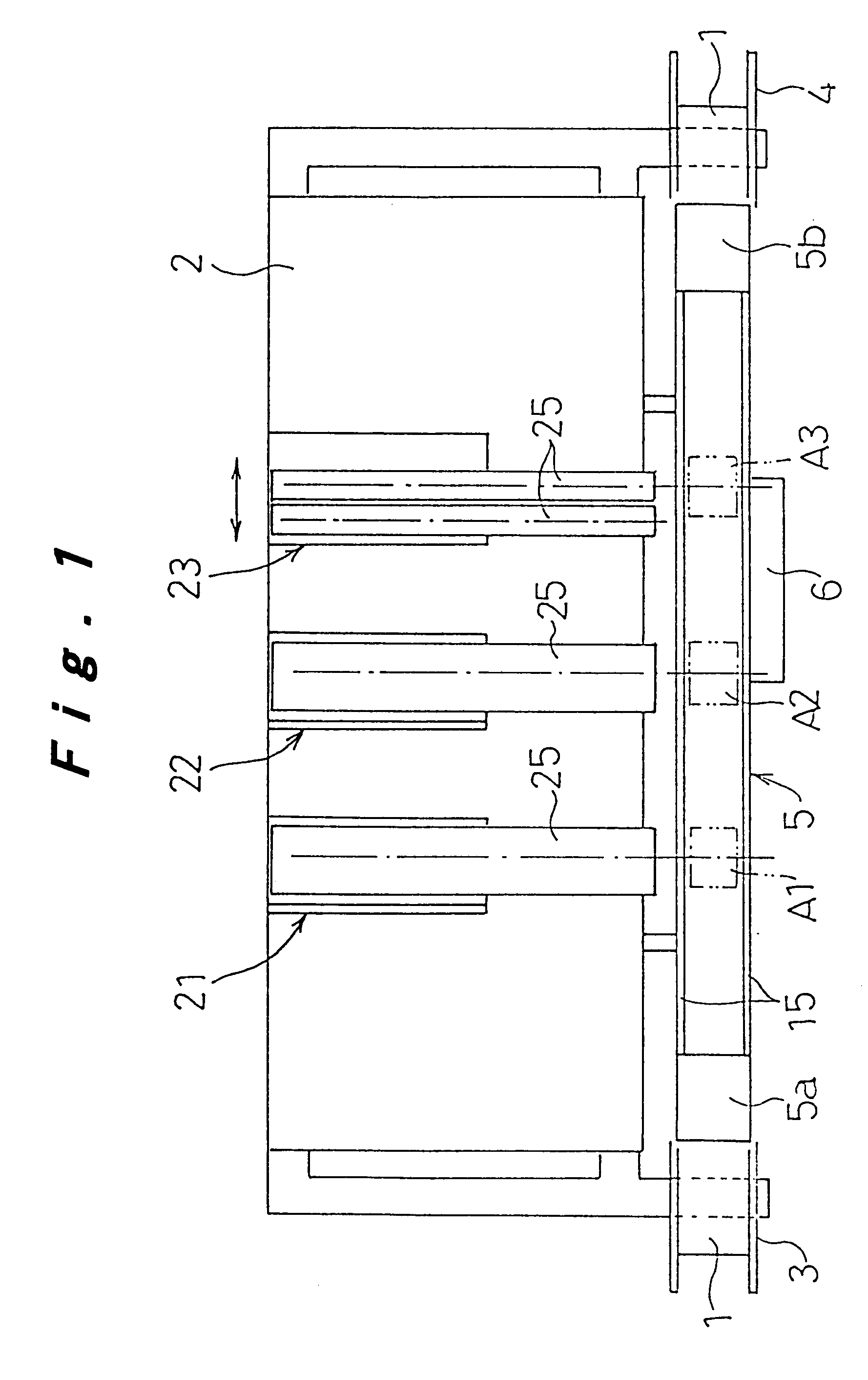
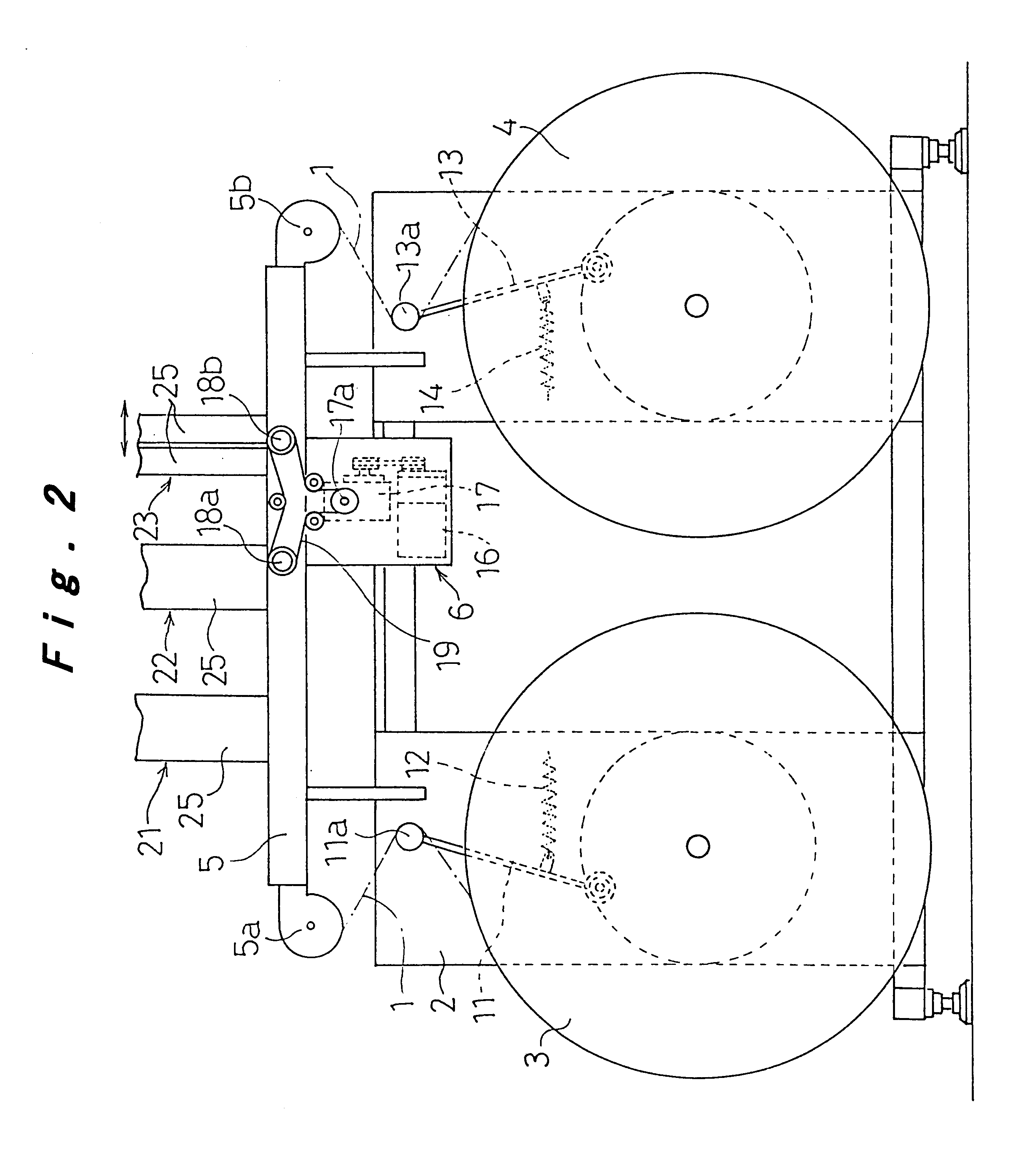
In FIGS. 1 and 2, a tape-like member 1, and a supply reel 3 and a take-up reel 4 for the tape-like member 1 are disposed in front on both sides of a table 2 of the assembling apparatus. A conveying path 5 is linearly arranged on the upper front of the table 2. The conveying path 5 allows the tape-like member 1 fed from the supply reel 3 to run therealong to the take-up reel 4. An intermittent conveying means 6 is provided on the way along the conveying path 5 for conveying the tape-like member 1 at intervals of a specific pitch.

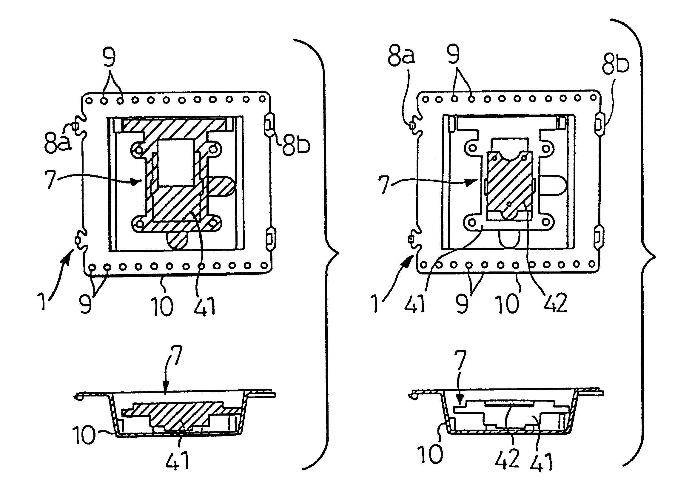
The tape-like member 1 of this embodiment comprises, as shown in FIG. 5, a succession of holder units 10 joined to each other by couplers 8a and 8b at either end to form a tape-like train, each of the holder units 10 having a holding recess 7 in the center for holding a product, and feeding perforations 9 at both side edges thereof.

A g...

second embodiment

Next, the component assembling apparatus according to the present invention will be described referring to FIGS. 6 to 13.

In FIG. 6, numeral 51 represents a table of the component assembling apparatus, on which at its front part a plurality of tape-like component feeders 52 and one or more product storing means 53 are disposed in parallel such that their respective component feeding positions 52a and product receiving positions 53a are aligned in a straight line. An assembling base 54 is located behind and substantially in the center of the straight line along which the component feeding positions 52a of the tape-like component feeders 52 and the product receiving positions 53a of the tape-like product storing means 53 are aligned. Also, a transferring and assembling robot 55 which transfers components and products between the component feeding positions 52a, the product receiving positions 53a, and the assembling base 54 and performs necessary assembling actions is mounted on the ta...

third embodiment

the present invention will be described referring to FIG. 14. Like parts are given like numerals as those described in the second embodiment, and will be explained in no more detail but only different points. As compared with the second embodiment, in which the lens tube 62, first, second, and third lenses 63, 64, 65 are assembled together on the assembling base 54, this embodiment omits the assembling base 54 and allows the lens tube 62 and first, second, and third lenses 63, 64, 65 to be transferred, assembled together, and held in the product receiving recess of the tape-like member 71 in the product receiving means 53.

According to the third embodiment, if the tape-like member 71 is constructed such that its product receiving recesses are accurately designed and physically strong enough to resist external stresses, it will simplify the structure of the apparatus and reduce the number of transfer steps, by which further reduction of the assembling cost can be realized.

In this embo...


PUM

PropertyMeasurementUnit
tensionaaaaaaaaaa
depthaaaaaaaaaa
pulling forceaaaaaaaaaa

Abstract

Components (62-65) are consecutively taken out from a plurality of component feeders (52) which supply a multiplicity of components to a component feeding position (52a) in succession, transferred to a prescribed assembling position (54a, 154a, 157a), and assembled into a product (61), which is then transferred to and held in each of a multiplicity of holding recesses provided in a product storing means (53, 153). This method allows the components to be assembled into a product by a component assembling apparatus of compact and simple construction, as well as permits the assembled product to be held and carried in the holding recesses of the product storing means to the next step of the process.

Description

The present invention relates to a method of and an apparatus for assembling various components to make an assembled product in an automatic procedure with a tape member.A conventional component assembling apparatus includes a plurality of assembling stations aligned along an assembly line which comprises a conveyor(s) equipped with multiple assembling jigs. Each assembling station comprises assembly robots for supplying and mounting components in the assembling jigs and component feeders for feeding components to the assembly robots. Assembled products are transferred by robots from the assembling jigs to a holder or a receiver provided on a tray or a tape-like member which is in turn conveyed to a succeeding step of the assembly line.However, such conventional component assembling apparatus is bulky and elaborate in construction as it uses a full-scale assembly line with conveyors, and thus causes increase in the cost of installation. Also, there is an extra step required for conv...

Claims


Application Information

Patent Timeline
Patent Type & Authority Patents(United States)
IPC IPC(8): H05K13/04
CPCH05K13/04H05K13/0417Y10T29/53261Y10T29/53187Y10T29/49829Y10T29/53539H05K13/003H05K13/021
Inventor ISHII, YOSHIMICHIMOCHIZUKI, HIROYUKI
Owner PANASONIC CORP
Why Eureka
Try Eureka