Cycle control system for boiler and associated burner

a control system and boiler technology, applied in water feed control, lighting and heating apparatus, instruments, etc., can solve problems such as boiler explosions, water level in the boiler may drop below the sensor to an unsafe operating level, and the aforementioned probe-type cut-off is limited in its ability to sense the true water level

Inactive Publication Date: 2002-05-21
COWLES OPERATING CO
View PDF40 Cites 63 Cited by
  • Summary
  • Abstract
  • Description
  • Claims
  • Application Information

AI Technical Summary

Benefits of technology

The timing circuit also includes a burner monitor circuit having an input for monitoring when the burner is on and off as a result of the demand control. The on-period timer is reset by the timing circuit whenever the burner monitor circuit indicates the demand control circuit has turned off the burner for a length of time sufficient to allow foam and surging fluid in the boiler to settle. This avoids prematurely turning off the burner to check the water level immediately after the burner has been off under the demand control for long enough to accomplish that check.

Problems solved by technology

Failure to maintain this minimum water level within the boiler can result in severe boiler damage and in some circumstances, can lead to boiler explosions.
Under some operating conditions, common in poorly maintained boilers, the aforementioned probe-type cut-offs are limited in their ability to sense the true water level.
For example, in extreme conditions, the water level in the boiler may drop below the sensor to an unsafe operating level.
The problem described above is becoming more acute as the industry moves to smaller, more efficient boilers.
Since these newer boilers have considerably lower water content than boilers manufactured years ago, contamination and foaming occur more quickly.
In addition, since these boilers hold less water, they are more susceptible to low water conditions.
Although the water level is constantly being monitored by the probe, the true water level can only be accurately determined when the foam has settled and the water has stopped moving.
It is particularly undesirable to turn off the burner while the boiler system is attempting to meet demand, if it is unnecessary.
Another difficulty with the constant independent cycling of prior foam compensating burner control system designs has occurred when the boiler fluid is at a low temperature, as occurs during initial heating, or during long periods of very heavy demand.

Method used


Image

  • Cycle control system for boiler and associated burner
  • Cycle control system for boiler and associated burner
  • Cycle control system for boiler and associated burner

Examples


Embodiment Construction

)

In describing the preferred embodiment of the present invention, reference will be made herein to FIGS. 1-2 of the drawings in which like numerals refer to like features of the invention.

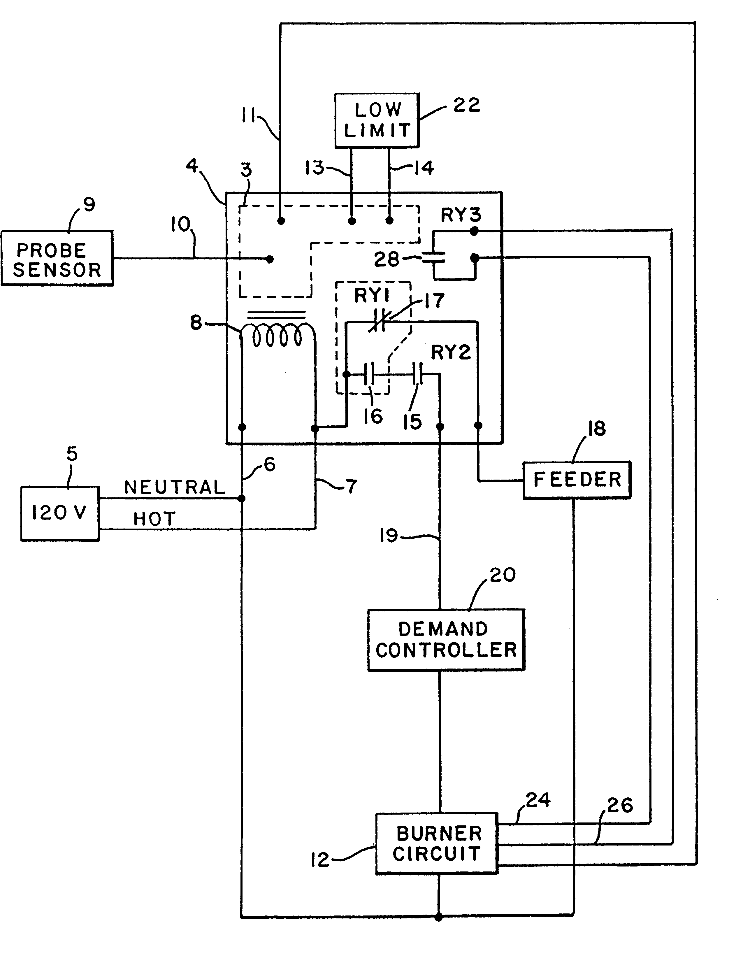
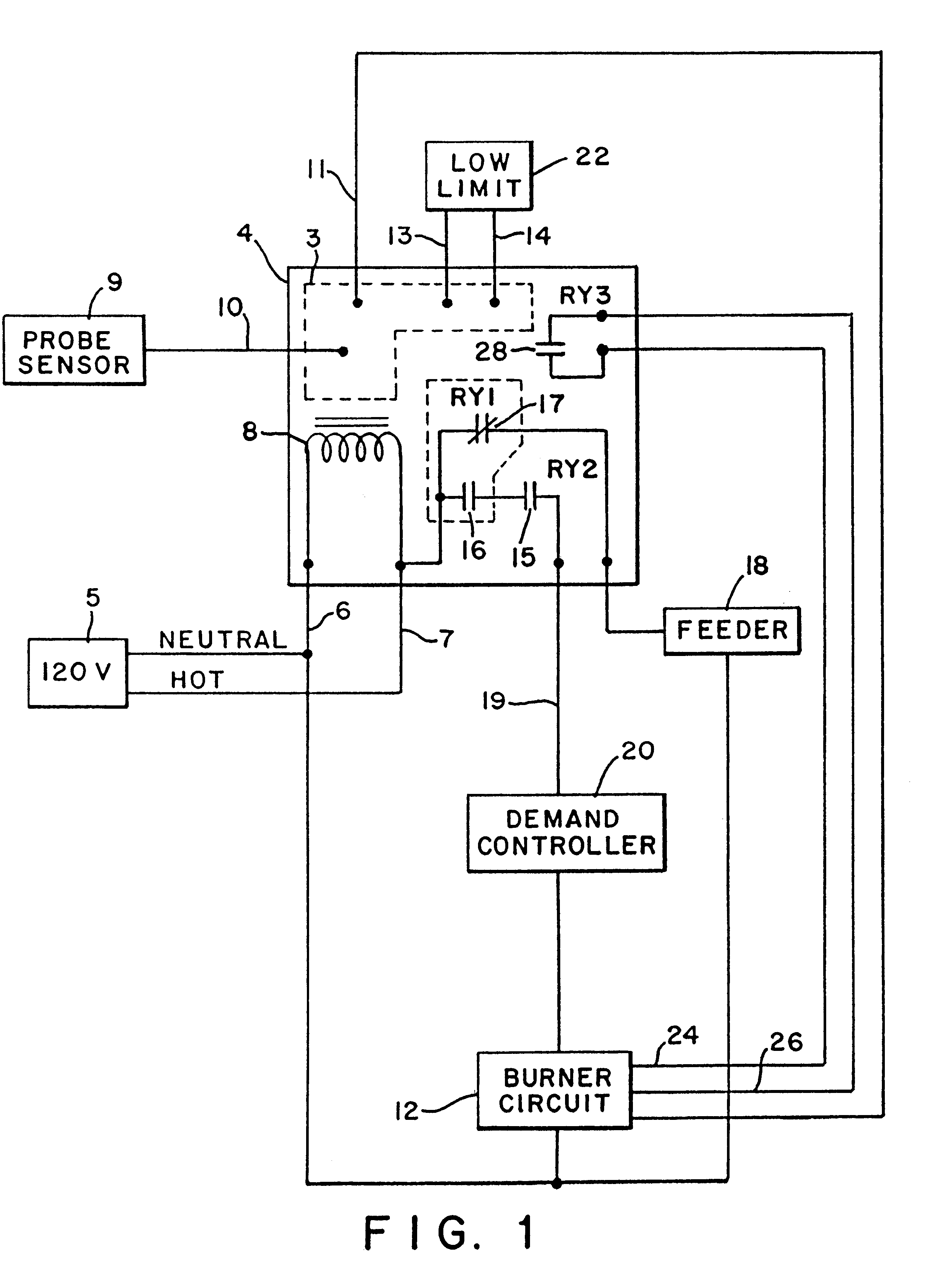
FIG. 1 provides a circuit diagram showing how the cycle control system of the present invention is interconnected to a boiler having a burner and a demand control system to turn the burner on and off responsive to demand. The cycle control system includes a timer circuit 3 constructed on a circuit board 4 which is powered by connection to AC power 5 with power leads 6 and 7.

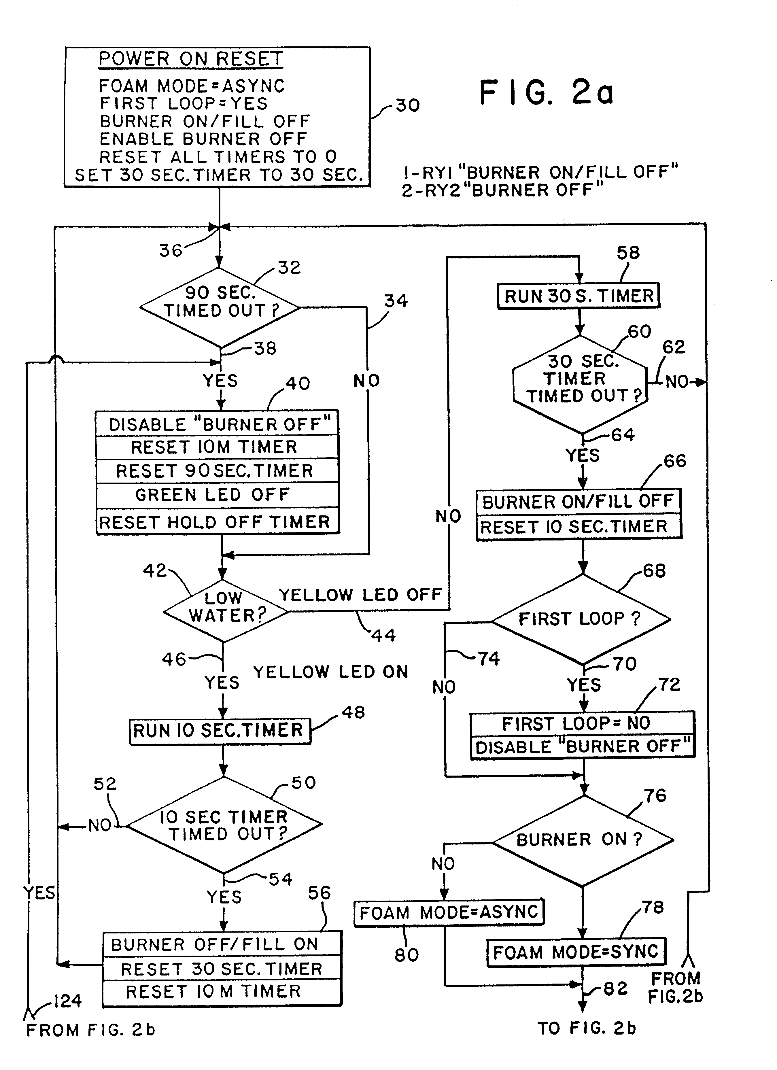
A transformer 8 is used to provide power to the timing circuit 3. Conventional voltage regulation is used to produce the necessary power for the timing circuit, which is preferably constructed conventionally as a digital controller using a microprocessor implementing the program defined in the flow chart seen in FIGS. 2a and 2b.

Timing circuit 3 is connected to a water level probe sensor 9 via input 10 that allows the timing circ...


PUM


Abstract

A cycle control system for use with a boiler having a fluid therein and a method of monitoring a boiler to determine the presence of an adequate level of fluid therein. The cycle control system includes a timing circuit producing a burner control signal having alternating on and off states corresponding to on and off period timers to allow foam to settle so that a probe can accurately check the fluid level in the boiler. A burner monitor circuit monitors when a demand controller turns the burner on and off responsive to demand. The on-period timer is reset whenever the burner monitor circuit indicates the demand control circuit has turned off the burner for a length of time sufficient for the probe to accurately check the fluid level.

Description

1. Field of the InventionThe present invention is related to control systems for use with boilers and their associated burners. More specifically, the present invention is directed to foam compensating control systems that periodically turn the burner off to diminish foam and surging in the boiler and allow the true water level to be accurately determined.2. Description of Related ArtSteam boilers require a minimum level of water to function properly and safely. Failure to maintain this minimum water level within the boiler can result in severe boiler damage and in some circumstances, can lead to boiler explosions.A common method of monitoring the water level in a steam boiler is the electronic probe-type low water cut-off. This device shuts down the burner in the event that the water falls below the lowest safe level. Such a system uses an electronic probe that measures conductivity between two electrodes. One electrode protrudes directly from the probe into the boiler through a ta...

Claims


Application Information

Patent Timeline
Patent Type & Authority Patents(United States)
IPC IPC(8): F22B37/00F22B37/78G01F23/00G05D9/00G05D9/12
CPCF22B37/78G05D9/12G01F23/0007
Inventor LYONS, RICHARD A.MURRAY, CHRISTOPHER L.
Owner COWLES OPERATING CO
Why Eureka
Try Eureka