
Coaxial cavity resonator

Inactive Publication Date: 2002-05-28
INTEL CORP
View PDF2 Cites 19 Cited by
  • Summary
  • Abstract
  • Description
  • Claims
  • Application Information

AI Technical Summary

Benefits of technology

The invention has the advantage that because of the manner of increasing the capacitance, the resonator can be made substantially smaller than a prior art quarter-wave resonator, which has the same Q-value. The improvement achieved can also be used partly for saving space and partly for maintaining a high Q-value compared to the Q-value for a resonator with a single top capacitance, such as a tuning screw.
Furthermore, a smaller resonator according to the present invention has the advantage to allow the volume of the cavity to be substantially smaller for a specific frequency, compared to prior art solutions.
In addition, the invention has the advantage that when the resonator is shortened it becomes mechanically stronger and therefore also more stable with regard to its electrical properties. Support pieces that increase the dissipation are not needed in it, either.

Problems solved by technology

Resonators of this kind entail the drawback of internal dissipation of the components and therefore clearly lower Q-values compared to the other types.
The drawback is radiation dissipation caused by the open construction and thus relatively low Q-values.
When a twin cable or coaxial cable is used, the drawback is relatively high dissipation and a relatively poor stability.
The construction can also be unpractical large.
However, this leads to an increase of resistive dissipation.
In addition, because of the reduction in the thickness of the construction, it may be necessary to support the inner conductor by a piece made of a dielectric material, which causes considerable extra dissipation in the form of dielectric loss and increases the manufacturing costs.
Thus the size of the resonator is reduced, but the clearly increased dissipation is a drawback.
However, their size is a drawback when the aim is to minimise the size of the construction.
On the other hand, dielectric resonators have the drawback of relatively high manufacturing costs.
A drawback with this type of multiple disc resonator is that the Q-value of the resonator decreases compared to the Q-value of the hat resonator.
Although this resonator has a reduced size it is still fairly large in size and will have the drawback of being mechanical unstable if the volume of the cavity is reduced, due to the design of the conductive body.

Method used


Image

  • Coaxial cavity resonator
  • Coaxial cavity resonator
  • Coaxial cavity resonator

Examples


Embodiment Construction

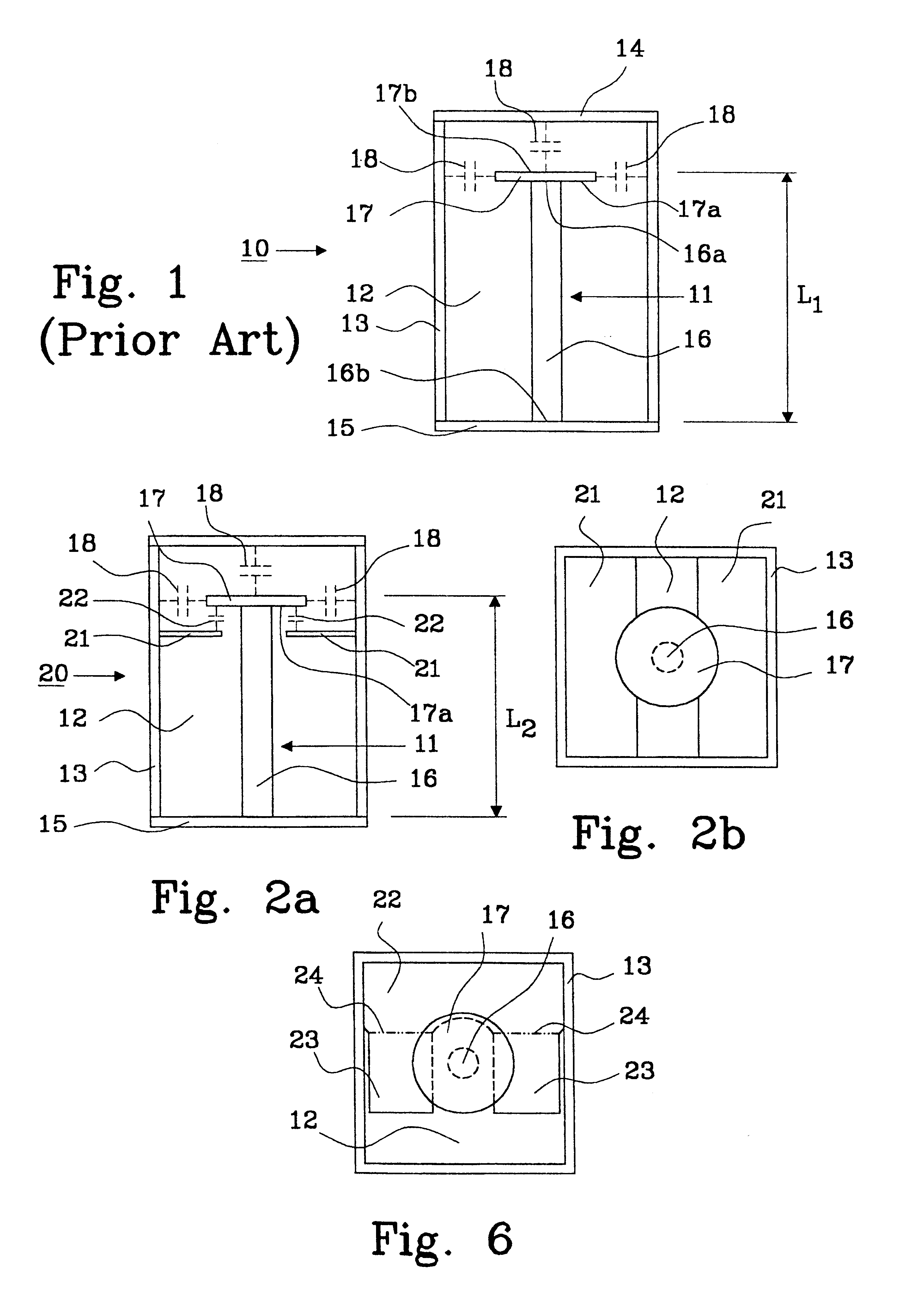
FIG. 1 shows a hat resonator 10 according to prior art. It includes, among other things, a conductive body 11 located inside a cavity 12. The cavity 12 having side walls 13, a top wall 14 and a bottom wall 15. The conductive body 11 comprises a conductor rod 16 and a main conductor disc 17. An end 16a of the rod 16 is connected to a first side 17a of the main disc 17. A free end 16b of the conductor rod 16 is in short-circuit connection with the bottom wall 15 of the cavity 12. A second side 17b, opposite the first side 17a, of the main disc 17 is in open-circuit relation with the top wall 14 of said cavity 12. Capacitive coupling 18 between the disc 17 and the top wall 14 and side walls 13 of the cavity 12 shortens the required length L.sub.1 of the conductive body 11 for operation at a specific frequency.

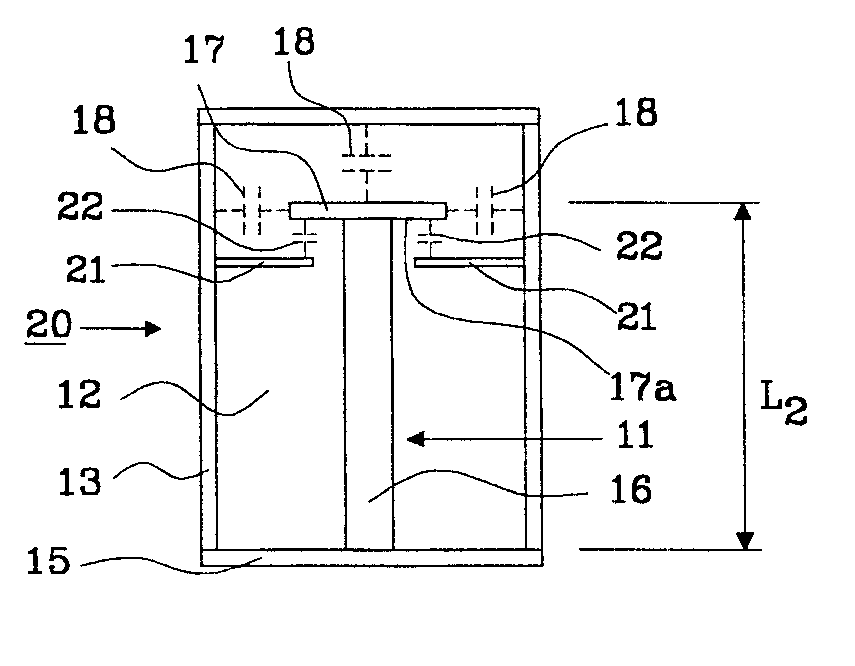
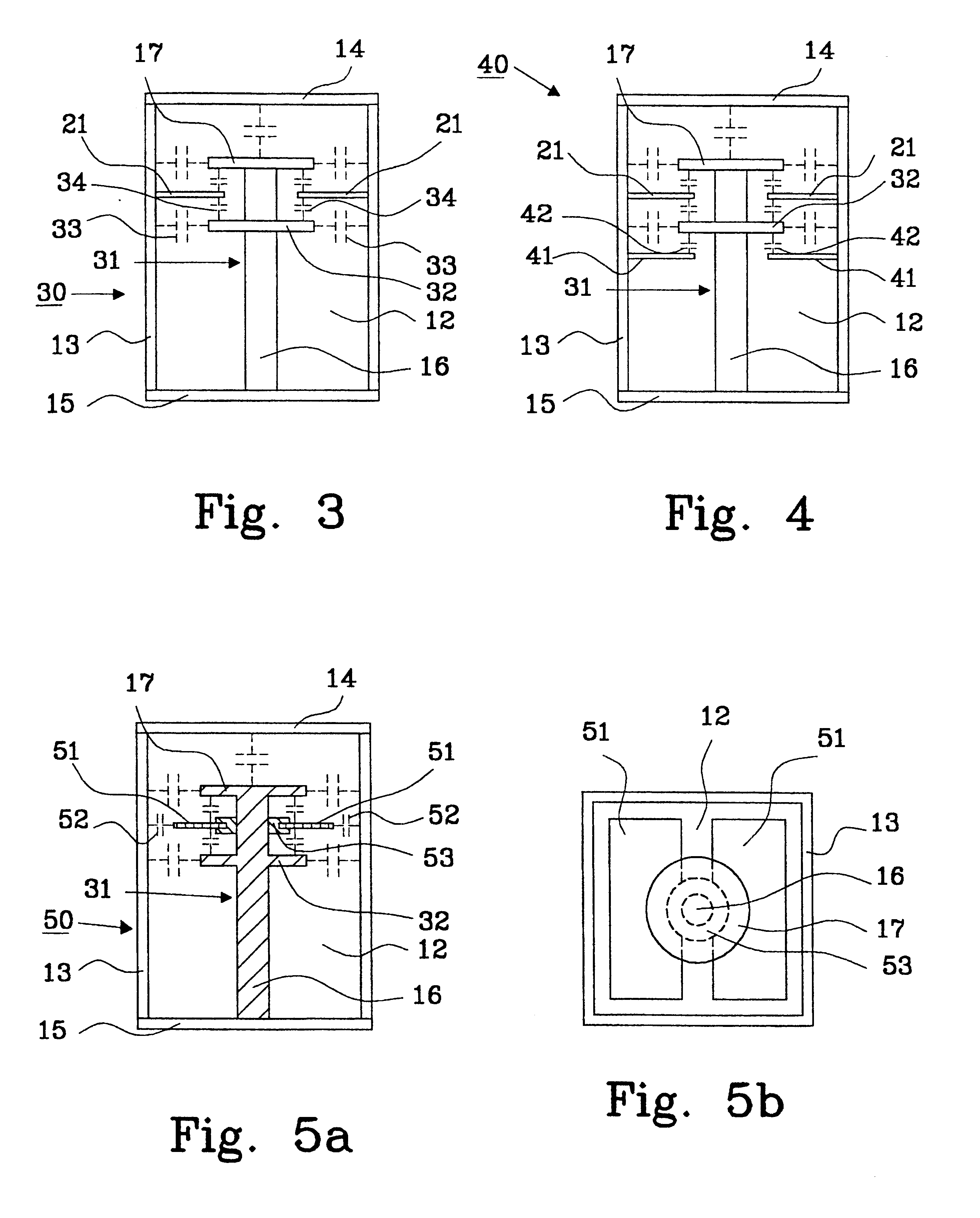
FIGS. 2a and 2b shows an improved embodiment of a hat resonator 20 according to the present invention, where one or more plates 21 are located in the cavity 12. The plate (s) 21 a...


PUM


Abstract

The construction is a coaxial cavity resonator (20, 30, 40, 50) comprising at least one conductive body (11, 31), which body is open at one end and shortened from a quarter-wave resonator. The conductive body includes a main rod (16), which is in one end attached to the cavity wall (15), and a main disc (17) attached to the free end of the main rod (16). The cavity (12) further comprises one or more conductive plates (21, 41, 51) located between the main disc (17) and the side walls (13), at the first side (17a) of, and out of galvanic contact with, the main disc (17). The shortening is carried out by creating air-insulated extra capacitance between the resonator cavity walls via the conductive plates and a mechanical structure at the open end of the conductive body.

Description

The present invention relates to a coaxial cavity resonator defined in the preamble of claim 1, which is particularly suitable for a structural part of a filter in radio devices.BACKGROUND TO THE INVENTIONResonators are used as the main structural part in the manufacture of oscillators and filters. The important characteristics of resonators include, for example Q-value, size, mechanical stability, temperature and humidity stability and manufacturing costs.The resonator constructions that are known so far include the following:1) Resonators Compiled of Discrete Components, Such as Capacitors and InductorsResonators of this kind entail the drawback of internal dissipation of the components and therefore clearly lower Q-values compared to the other types.2) Microstrip ResonatorsA microstrip resonator is formed in the conductor areas on the surface of a circuit board, for example. The drawback is radiation dissipation caused by the open construction and thus relatively low Q-values.3) ...

Claims


Application Information

Patent Timeline
IPC IPC(8): H01P7/04
CPCH01P7/04H01P7/06
Inventor RATY, TUOMOKANERVO, ANTTI
Owner INTEL CORP
Learn More