Piezoelectric rotational accelerometer

Inactive Publication Date: 2002-06-04
KISTLER INSTR
View PDF8 Cites 64 Cited by
  • Summary
  • Abstract
  • Description
  • Claims
  • Application Information

AI Technical Summary

Benefits of technology

A typical model of a shear-type linear accelerometer is described in U.S. Pat. No. 5,512,794 to Kubler, et al., shown in FIG. 1 as prior art, known as a K-Shear accelerometer from Kistler Instrument of Amherst, N.Y. The K-Shear accelerometer is sturdy and well-suited for high-frequency t

Problems solved by technology

Mechanical structures deform dynamically at resonant frequencies and the resulting stresses can cause tremendous damage.
Attachments such as welds, joints, bolts or the like can introduce significant error into the FEA model because the required stiffness estimates are generated from engineering judgement and empirical data.
A spatially narrow array provides a means to estimate rotations; however, measuring rotations still presents a great deal of difficulty at interfaces such bolted joints.
Unfortunately, measuring this dynamic rotational data has not been straightforward due to the lack of convenient and accurate rotational accelerometers.
However, a problematic fact is the prevailing levels of output signal generated by the translational movement tends to overshadow those due to rotational motions.
This makes the differencing operations above liable to serious error.
The addition of these post-processing components necessarily introduces numerous aspects of error into the design.
This is not a simple task bec

Method used


Image

  • Piezoelectric rotational accelerometer
  • Piezoelectric rotational accelerometer
  • Piezoelectric rotational accelerometer

Examples


second embodiment

IONAL ACCELEROMETER

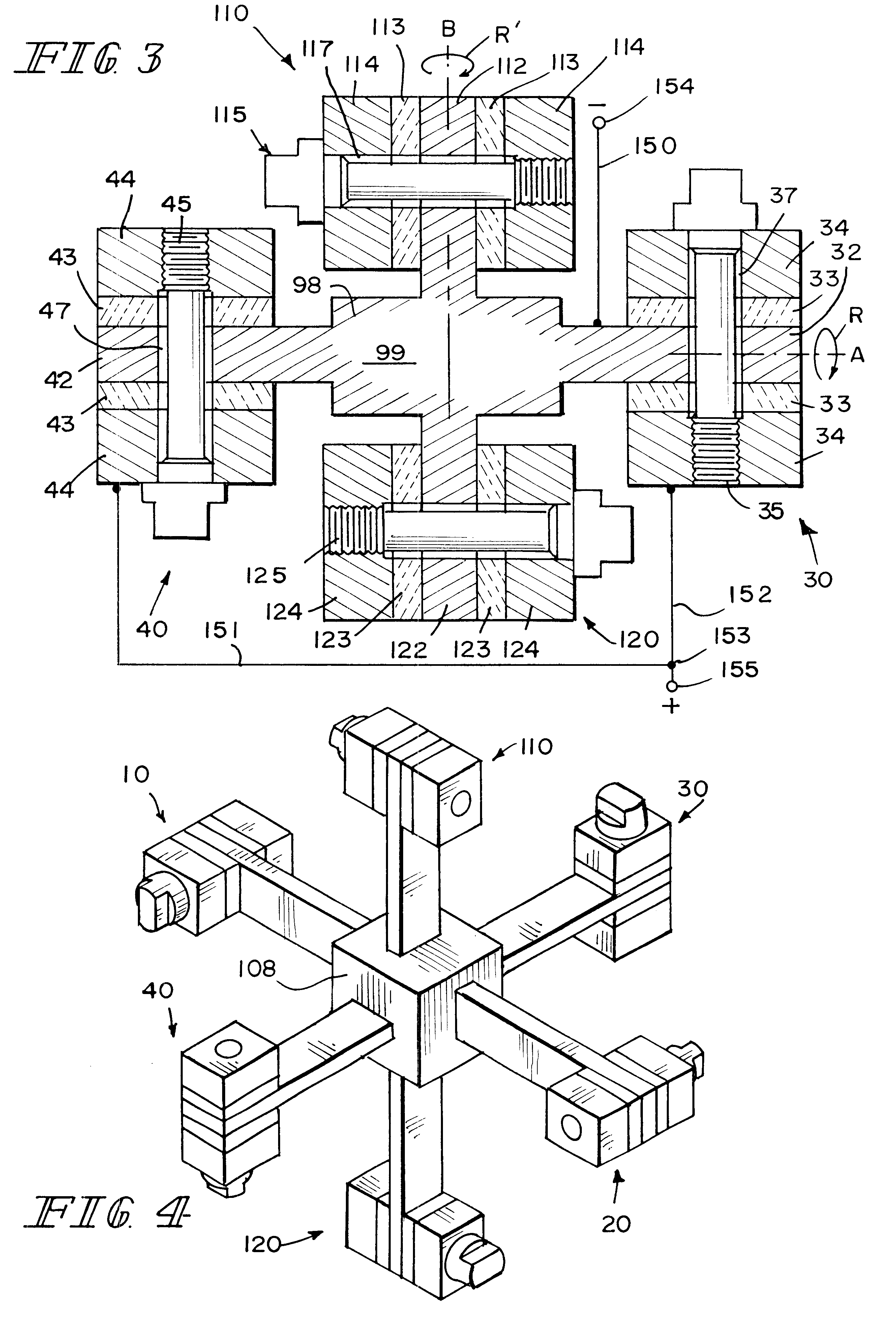
A double-axis rotational accelerometer may be constructed by adding third and fourth spaced-apart linear accelerometer halves, aligned so that the first, second, third and fourth accelerometers halves have mutually parallel axes of sensitivity. Each of the third and fourth linear accelerometer halves have at least one piezoplate and at least one seismic mass firmly clamped to the piezoplate.

The rigid connection between the third and fourth linear accelerometer halves defines a second axis perpendicular to the first axis. The polarity of the third and fourth linear accelerometer halves is reversed such that each half will output a signal of like polarity when subjected to rotation about the second axis.

The rigid connection has a body connected to the first and second linear accelerometer halves and a third post extending from the body and mutually perpendicular to the body and the first post as well as a fourth post extending from the body substantially collinear t...

third embodiment

TIONAL ACCELEROMETER

A third pair of linear shear accelerometer halves may be added in order to create a rotational accelerometer capable of measuring rotation about a third axis. This embodiment comprises each of the elements of the double axis rotational accelerometer, and adds fifth and sixth spaced-apart linear accelerometer halves, aligned to have parallel axes of sensitivity, wherein each of the fifth and sixth linear accelerometer halves having at least one piezoplate and at least one seismic mass firmly clamped to the piezoplate. A rigid connection between the fifth and sixth linear accelerometer halves, thereby defining a third axis mutually perpendicular to the first and second axes. The polarity of the fifth and sixth linear accelerometer halves is reversed such that each accelerometer half will output a signal of like polarity when subjected to rotation about the second axis.

The body is connected to the first, second, third and fourth linear accelerometer halves, and a fi...


PUM


Abstract

A rotational accelerometer using piezoelectric material, preferably quartz, in a shear orientation. Piezoplates and conducting seismic masses, each having bores therethrough, are bolted to posts that are symmetrically mounted to a body in such a manner that the bolt passes through the piezoplates but does not make contact. The accelerometer can be assembled as a single-axis accelerometer by mounting a pair of posts symmetrically about the body along the measured axis; additionally, the accelerometer may be assembled as a double or triple axis accelerometer by symmetrically mounting additional pairs of posts to the body. The total weight of the seismic masses and the crystals of the shear-type accelerometer halves should be equal. The invention sets forth a novel rotational accelerometer that reduces or eliminates the need for signal-processing electronics.

Description

BACKGROUND AND SUMMARY OF INVENTIONThe present invention relates generally to accelerometers employing piezoelectric materials, and more specifically to shear piezoelectric sensors responsive to acceleration or vibration.The acceleration experienced by a rotating member or structure is often a very important parameter to consider during a system design. For example, an automobile crash imparts tremendous energy to the occupants and significant rotational inertia is also present. Mechanical structures deform dynamically at resonant frequencies and the resulting stresses can cause tremendous damage.A Finite Element Analysis (FEA) is typically employed to form a mathematical model of the system. This analysis relates the deformation at one surface of a discrete elemental section to the surface deformation at opposing and adjacent elemental surfaces by an appropriate stress strain relationship. As surface displacements and rotations are considered in the analysis where each of them repr...

Claims


Application Information

Patent Timeline
IPC IPC(8): G01P15/08G01P15/09G01P15/18
CPCG01P15/0888G01P15/18G01P15/0915
Inventor KINSLEY, NORTONINSALACO, MICHAEL D.
Owner KISTLER INSTR
Why Eureka
Try Eureka