Thermostat incorporating thin film carbon dioxide sensor and environmental control system

a carbon dioxide sensor and environmental control technology, applied in the field of improved co . sub . 2 detectors, can solve the problems of dangerous levels, high efficiency, and substantial closing of environmental conditioning systems, and achieve the effect of compactness and simpleness

Inactive Publication Date: 2002-06-04
ROSEN HOWARD B +1
View PDF4 Cites 197 Cited by
  • Summary
  • Abstract
  • Description
  • Claims
  • Application Information

AI Technical Summary

Benefits of technology

It is therefore a broad object of this invention to provide an improved CO.sub.2 detector which is sufficiently compact and simple as to be suitable for integration with a thermostat in a single housing.

Problems solved by technology

However, it has been observed that these highly-efficient, substantially closed, environmental conditioning systems have a serious drawback which can even reach dangerous levels.
It has been found that when the concentration of CO.sub.2 in a conditioned space reaches on the order of 1000 parts per million, breathing becomes noticeably more labored and difficult, particularly for those with breathing problems.
Higher concentrations exacerbate these problems and can reach dangerous levels.
Commercial CO.sub.2 detectors have been both bulky and have required fairly sophisticated support circuitry because the voltages (or other electrical parameter) generated by or measured across the conventional CO.sub.2 sensors, which vary in accordance with changes in CO.sub.2 concentration, do so only across a very narrow, low level range.
It will be apparent that such a CO.sub.2 sensor and its support circuitry cannot be integrated with a temperature sensing and control system in a single, compact environmental control unit housing.
It will also be apparent to those skilled in the art that such a CO.sub.2 sensor cannot be integrated with substantially all the circuitry and components of both the CO.sub.2 detection subsystem and the temperature sensing and control subsystem into a single integrated circuit.

Method used


Image

  • Thermostat incorporating thin film carbon dioxide sensor and environmental control system
  • Thermostat incorporating thin film carbon dioxide sensor and environmental control system
  • Thermostat incorporating thin film carbon dioxide sensor and environmental control system

Examples


Embodiment Construction

)

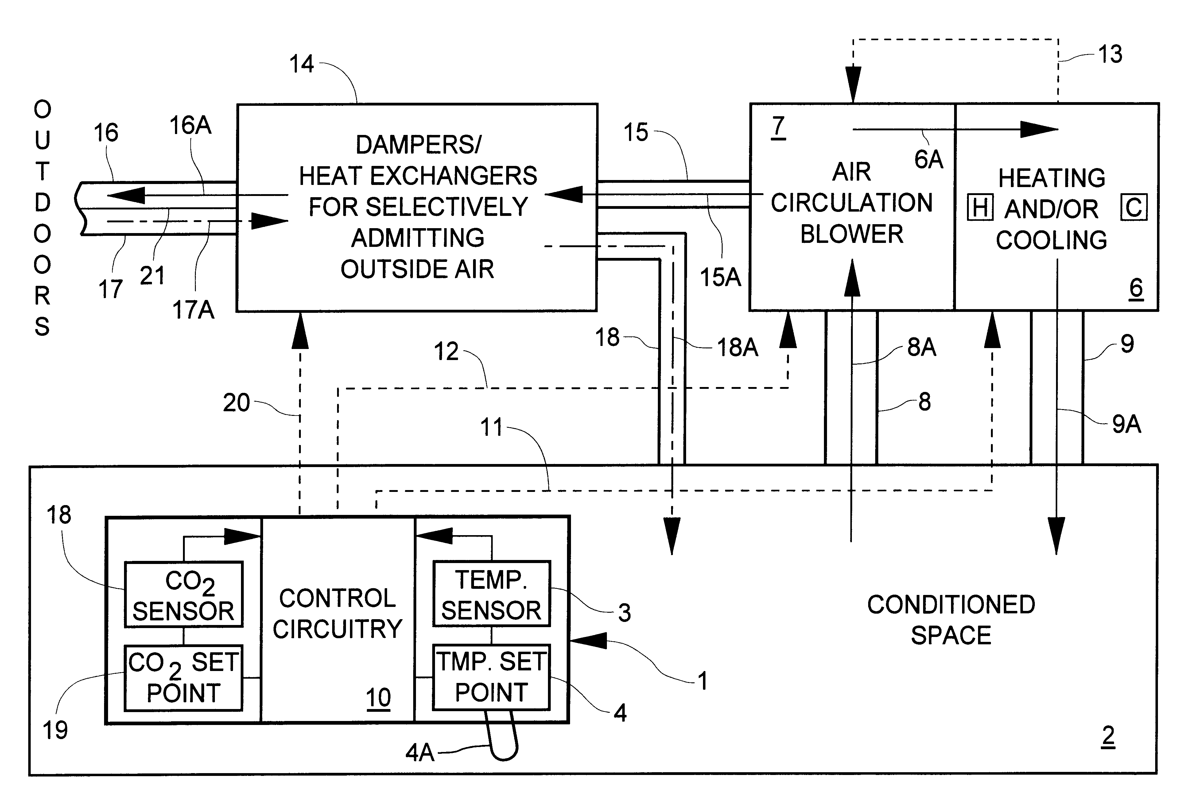
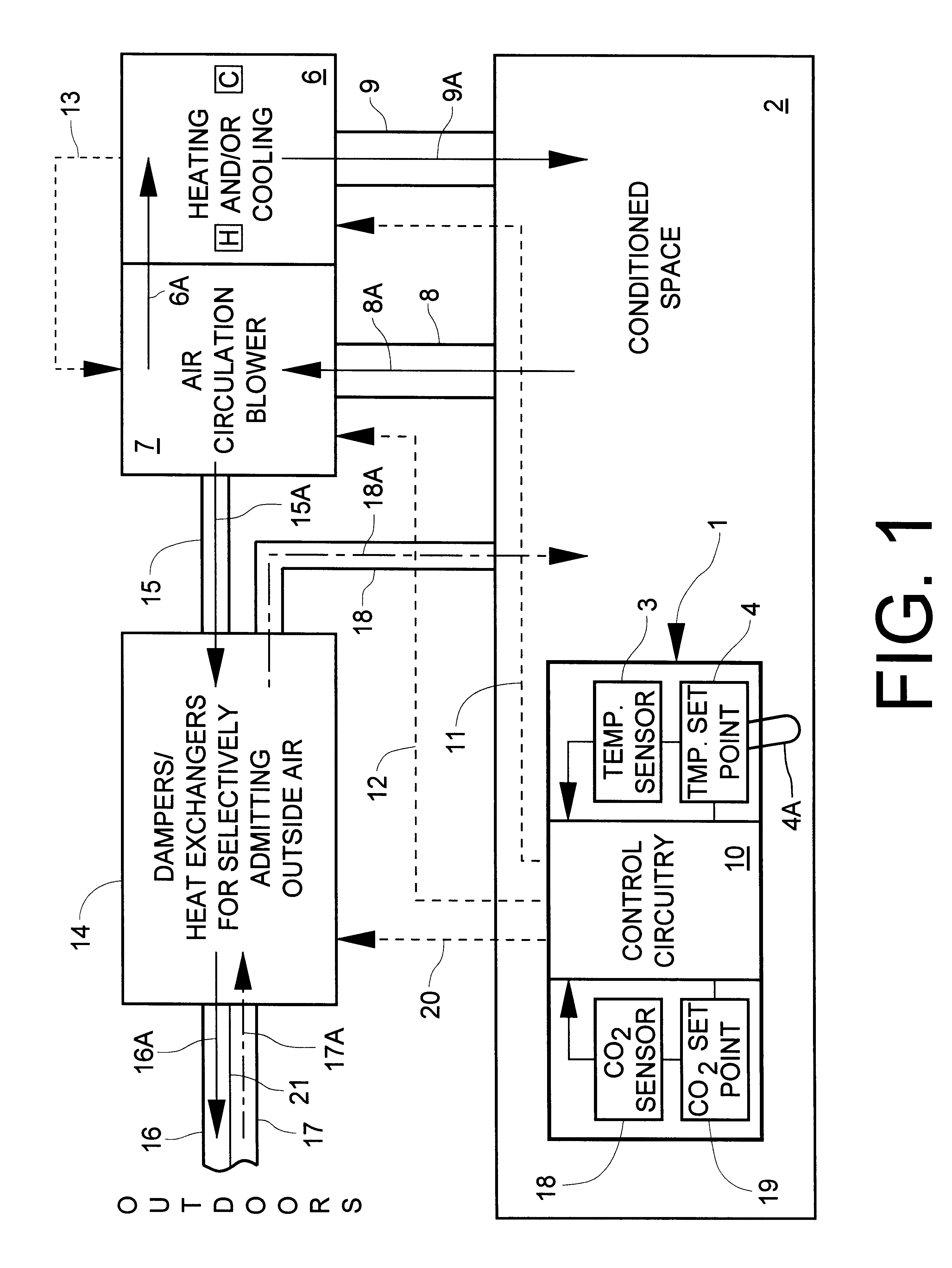
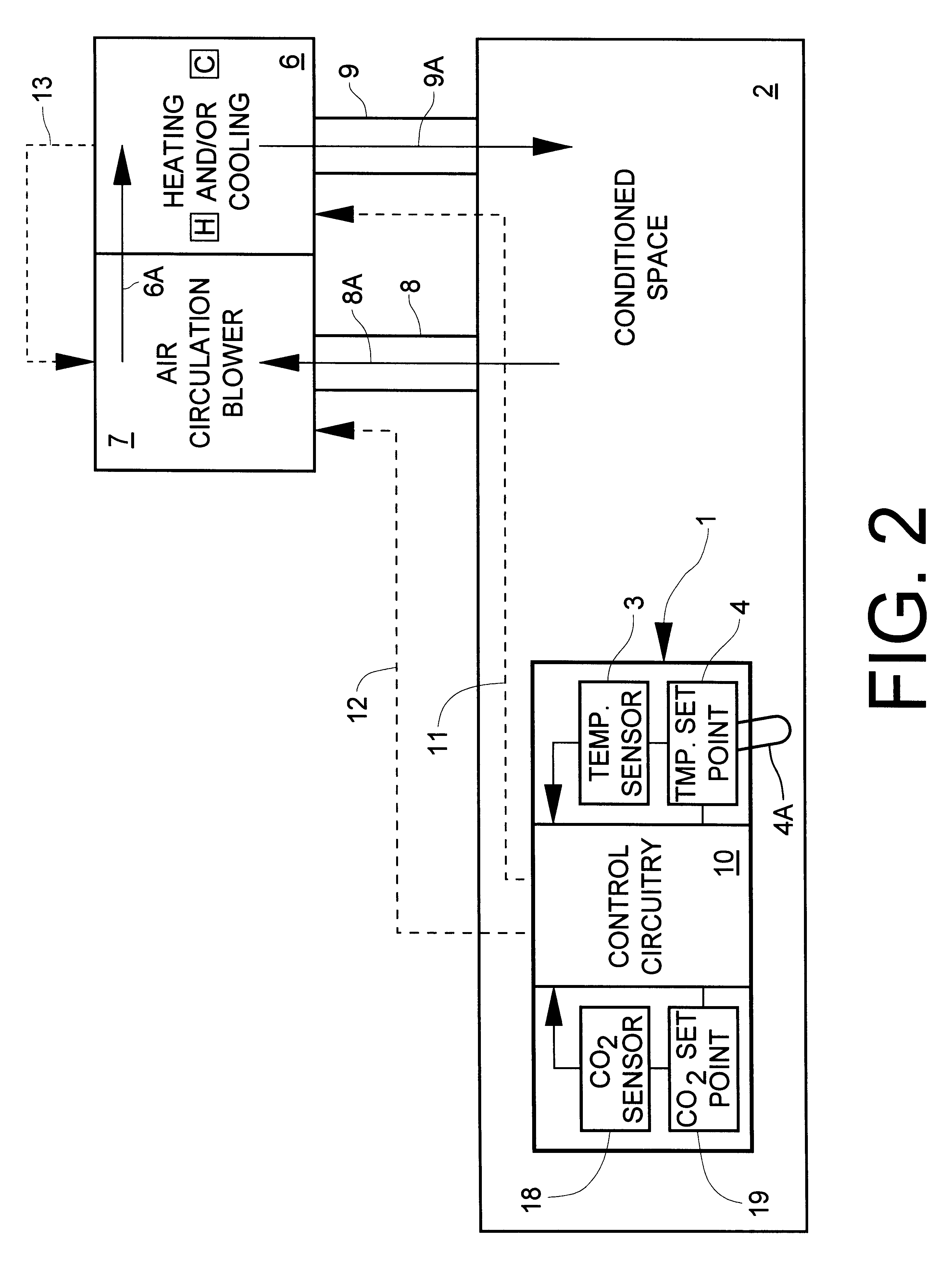
Referring first to FIG. 1, an integrated thermostat / CO.sub.2 level detector unit 1 is disposed within a conditioned space 2. The integrated unit 1 encloses both a conventional temperature sensor 3, an adjustable set point device 4 and control circuitry 5 which issues suitable control signals to heating and / or cooling unit 6 (generically, a temperature moderating unit) and blower unit 7 which serves to withdraw air from the conditioned space via conduit(s) 8 (represented by the arrow 8A), selectively force the air taken in through the heating and / or cooling unit 6 (represented by the arrow 6A) and back to the conditioned space 2 via conduit(s) 9 (represented by the arrow 9A).

Conventionally, control circuitry 10 reads the set point 4, typically established by manually adjusting movable element 4A, and the temperature in the conditioned space 2 is sensed by the sensor 3 in a manner which can be interpreted by the control circuitry 10 as representing a temperature which can be compared...


PUM


Abstract

A system for monitoring and modifying the quality and temperature of air within a conditioned space includes a blower unit, a damper unit for selectively admitting outside air into the conditioned space, a temperature moderating unit and a control unit. The control unit includes a thermostat and conventional temperature control apparatus for selectively activating the temperature moderating unit to maintain the desired temperature in the conditioned space. The control unit also incorporates CO2 concentration measuring and control apparatus which includes a small CO2 sensor. The CO2 sensor includes a cathode, an anode and a solid electrolyte disposed intermediate and electrically in contact with each of the cathode and the anode to effect a primary electrical cell. A heater and a heater thermostat serve to maintain the temperature of the cell at about 250° C. The cathode and anode materials and the chemical composition of the electrolyte are further selected such that the voltage generated across the heated cell varies in accordance with the CO2 concentration. CO2 concentration modifying apparatus is responsive to sensing a first predetermined CO2 concentration for turning on the blower unit and to sensing a second, higher, predetermined CO2 concentration for actuating the damper unit to admit outside air.

Description

This invention relates to the art of conditioning indoor living and working and other enclosed public spaces. More particularly, this invention relates to a system in which the carbon dioxide (CO.sub.2) level is monitored and controlled by apparatus in which the CO.sub.2 sensor and support circuitry is integral with a thermostat which also serves to conventionally control the temperature range within the conditioned space.The ever increasing cost of energy has resulted, in recent years, in the construction of homes and buildings which are very well insulated and, further, which carefully provide for keeping the air within the home or building well isolated from the encroachment of outdoor air. This latter feature serves to limit the adverse effect of outdoor air on the desired temperature intended to be maintained within the building occasioned by direct mixing with the indoor air, an effect which is in addition to and independent of the limitation of adverse conduction effects affo...

Claims


Application Information

Patent Timeline
Patent Type & Authority Patents(United States)
IPC IPC(8): F24F11/00
CPCF24F11/0017Y02B30/78F24F2011/0026F24F11/30F24F2110/50F24F2110/70Y02B30/70F24F11/80F24F11/76F24F11/62
Inventor ROSEN, HOWARD B.DUSHANE, STEVEN D.
Owner ROSEN HOWARD B
Why Eureka
Try Eureka