Method and a system for digitally linearizing an amplifier

Inactive Publication Date: 2002-06-04
ALCATEL LUCENT SAS
View PDF13 Cites 77 Cited by
  • Summary
  • Abstract
  • Description
  • Claims
  • Application Information

AI Technical Summary

Benefits of technology

In other words, the work is done on a model of the amplifier and not, as in above-mentioned Patent Document EP 522 706 A2, merely on a comparison between the input test signal and the corresponding output signal (i.e. the amplified test signal). It is important to note that the fact that a modelled amplifier is used makes it possible to obtain improved accuracy on the correction parameters to be applied to the input signal, and thus improved linearization of the amplifier. In

Problems solved by technology

In radiocommunications systems, the non-linearity of the amplifier in the radio transmission system is detrimental because it distorts the transmitted signal, thereby degrading the spectrum of the signal, and thus causing interference signals to be generated in channels adjacent to the working channel.
In other words, the non-linearity of the amplifier causes an increase in the level of transmission interference in the adjacent channels.
This gives rise to failure to comply with specifications aiming to limit interference.
Such failure to comply with the specifications is further accentuated when modulation having a non-constant envelope (which is more sensitive to non-linearity defects) is used upstream from the amplifier.
That first known solution suffers from the major drawback of degrading amplifier efficiency.
Thus, if such an amplifier is included in a mobile terminal, it reduces battery life between charges.
Unfortunately, the correction loop requires additional analog components which firstly suffer from defects affecting the performance

Method used


Image

  • Method and a system for digitally linearizing an amplifier
  • Method and a system for digitally linearizing an amplifier
  • Method and a system for digitally linearizing an amplifier

Examples


Example

The invention relates to a method and a system for digitally linearizing an amplifier.

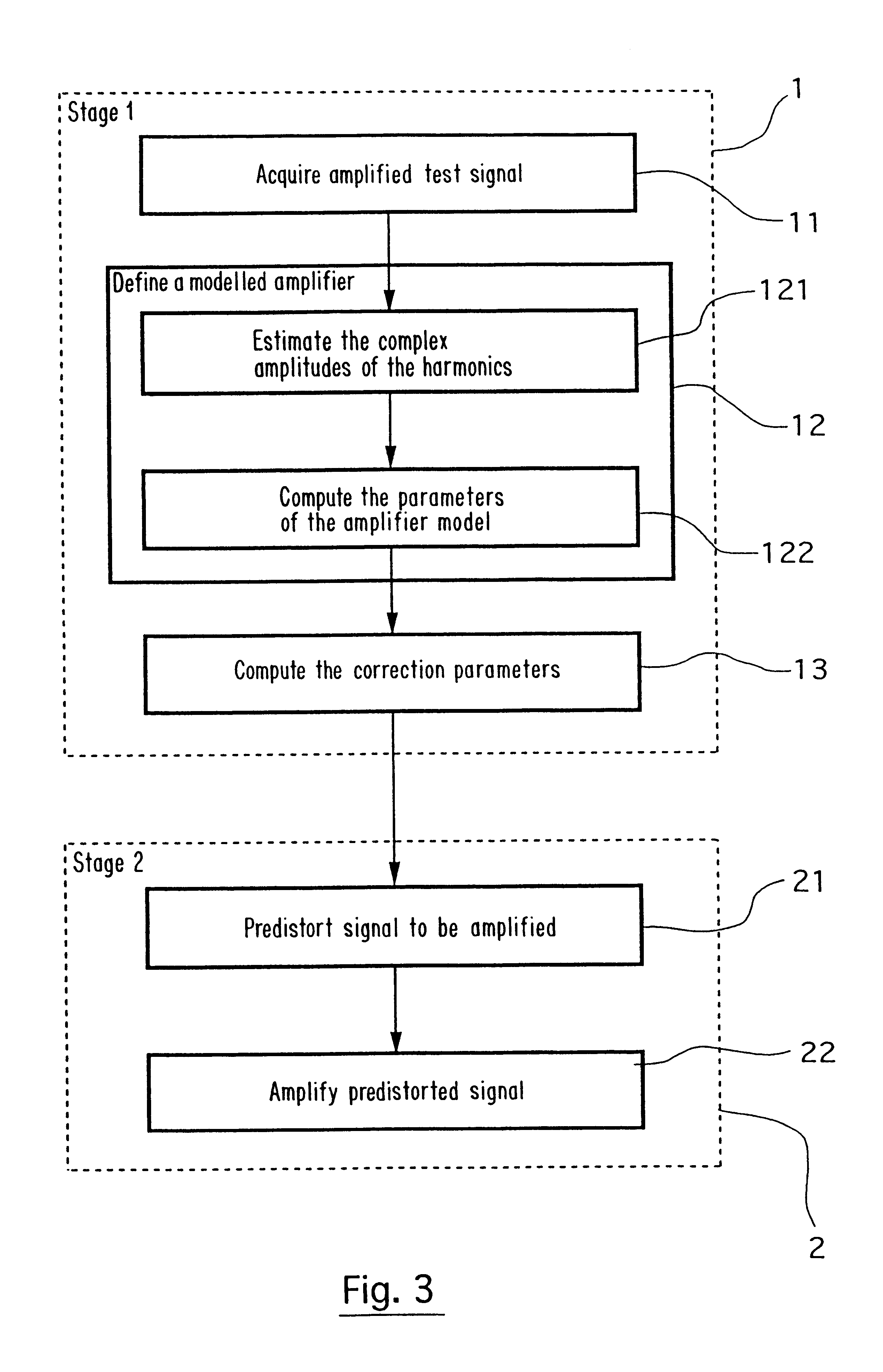
As shown in the flow chart of FIG. 3, the linearization method of the invention is of the type comprising two successive stages 1 and 2.

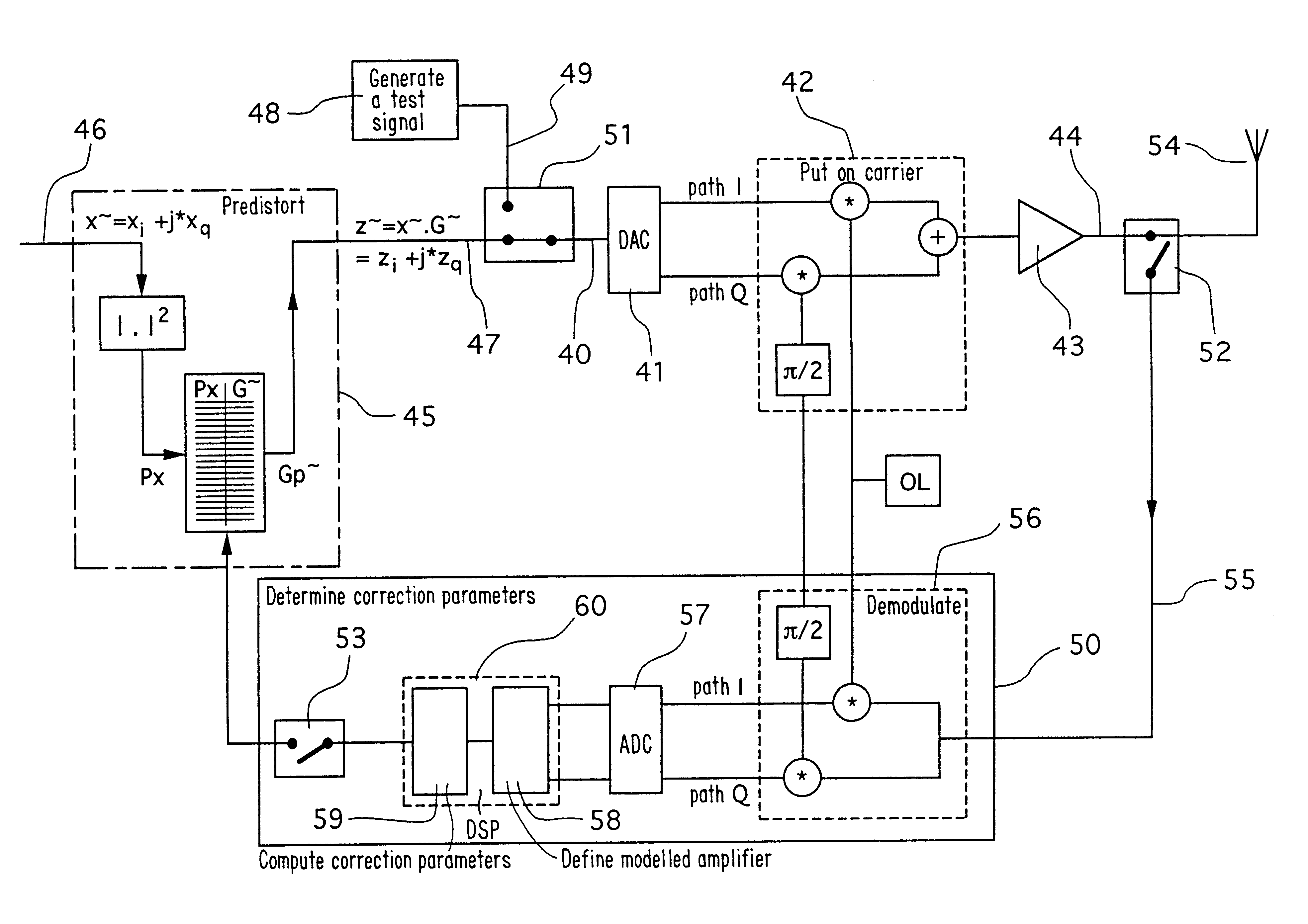
The purpose of the first stage 1 is to determine correction parameters for correcting the non-linearity of the amplifier. It is recalled that the correction defined by said parameters, which correction is intended to be used during the second stage 2 described in detail below, is predistortion having non-linearity that is the inverse of the non-linearity of the amplifier. The correction parameters are determined by applying a predetermined test signal to the input of the amplifier and by analyzing the signal obtained at the output (this signal being referred to as the "amplified test signal"). At the end of this first stage 1, the correction parameters are stored, e.g. in a "predistortion" table.

The purpose of the second stage 2 is to amplify a given signal linearl...


PUM


Abstract

The invention relates to a method of digitally linearizing an amplifier having non-linearity, the method being of the type comprising: a prior stage in which correction parameters for correcting said non-linearity are determined, and a linear amplification stage performed by applying predistortion followed by amplification. In the invention, stage in which the correction parameters are determined comprises the following steps: acquiring said amplified test signal in the form of samples in baseband; defining a modelled amplifier, by computing parameters of a predetermined amplifier model on the basis of said samples of the amplified test signal; and computing said correction parameters on the basis of said modelled amplifier so that they make it possible to linearize said modelled amplifier. The invention also relates to a corresponding system for digitally linearizing an amplifier.

Description

The invention relates to the field of amplifiers.More precisely, the invention relates to a method and a system for linearizing an amplifier.The invention is particularly, but not exclusively, applicable to linearizing amplifiers used in cellular radiocommunications systems (such as, in particular, the Global System for Mobile communications 900 MHz (GSM 900) (a public radiccommunications system operating in the 900 MHz band), the Digital Cellular System 1800 MHz (DCS 1800), the Personal Communication System (PCS), IS95, the Universal Mobile Telephone System (UMTS), the International Mobile Telecommunications 2000 system (IMT-2000), CDMA-One, etc.A mobile terminal generally includes an amplifier in its transmission system.Frequently, it is desirable to obtain linear amplification. Since an amplifier is never exactly linear, it is necessary to linearize the amplifier.In radiocommunications systems, the non-linearity of the amplifier in the radio transmission system is detrimental bec...

Claims


Application Information

Patent Timeline
IPC IPC(8): H03F1/32
CPCH03F1/3247H03F1/3294H03F1/3258H03F2201/3233
Inventor GOURGUE, FREDERICSOULA, VERONIQUE
Owner ALCATEL LUCENT SAS
Why Eureka
Try Eureka