Management of an air purification system with thermal regeneration

a technology of air purification system and thermal regeneration, which is applied in the direction of separation process, liquefaction, lighting and heating apparatus, etc., can solve the problems of increasing equipment complexity, blockage problems in equipment, especially heat exchangers, etc., and achieve the effect of reducing the amount of energy consumed

Inactive Publication Date: 2002-06-11
LAIR LIQUIDE SA POUR LETUDE & LEXPLOITATION DES PROCEDES GEORGES CLAUDE
View PDF16 Cites 63 Cited by
  • Summary
  • Abstract
  • Description
  • Claims
  • Application Information

AI Technical Summary

Benefits of technology

In contrast, the present invention aims to improve the known gas purification processes, par

Problems solved by technology

This is because, in the absence of such an air purification treatment for removing its CO.sub.2 and water impurities, there will be condensation and/or solidification of these impurities while cooling the air to cryogenic temperature

Method used


Image

  • Management of an air purification system with thermal regeneration
  • Management of an air purification system with thermal regeneration

Examples


example 2

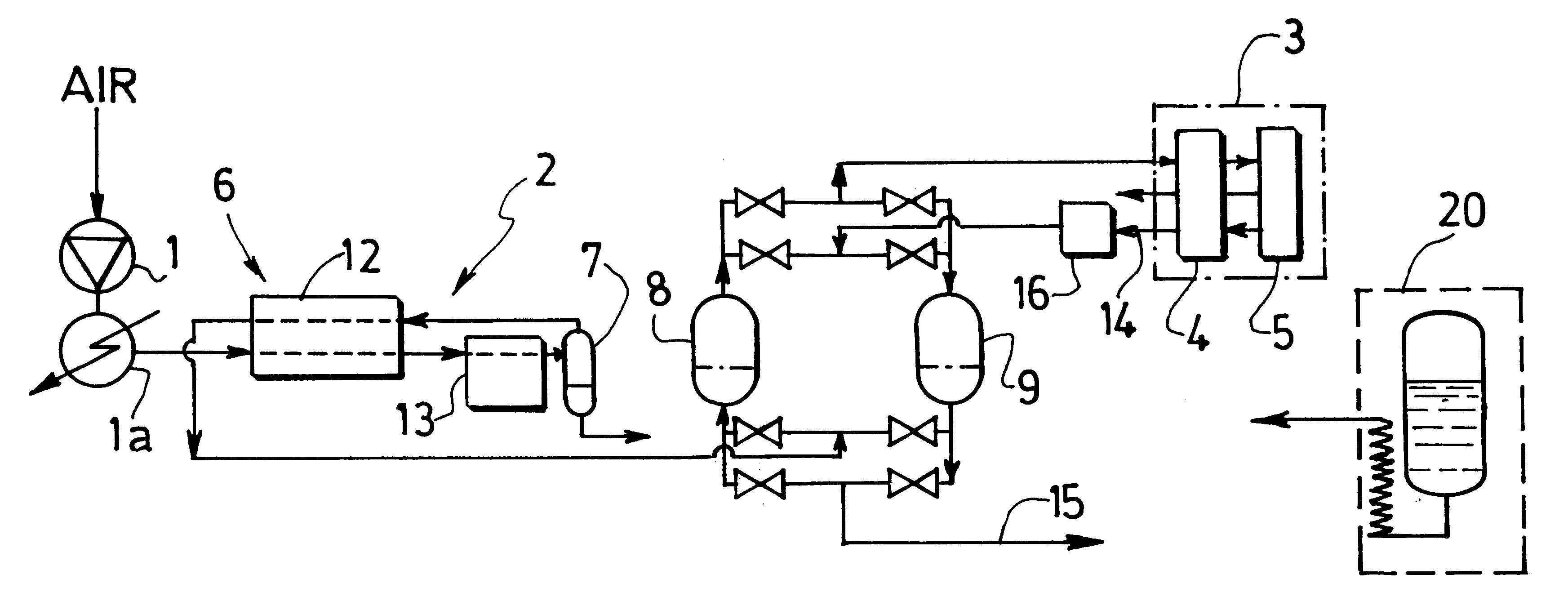
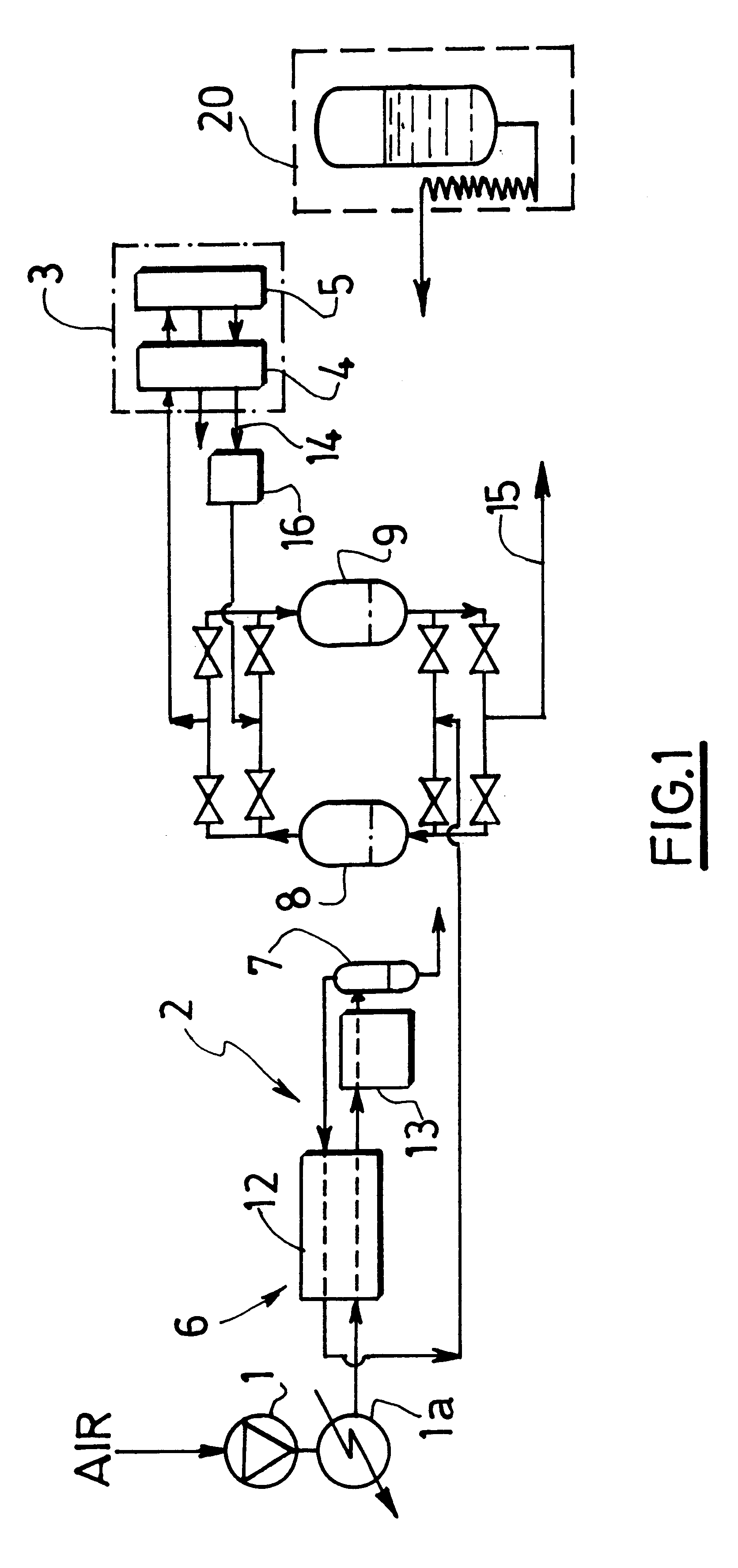
This example relates to the TSA-type purification for a large-capacity ASU. In this case, the energy consumption due to the regeneration becomes considerable in absolute terms and the system for adapting the cycle to the actual operating conditions is more sophisticated than that described above.

Instead of keeping the duration of the steps constant and of only varying just the power of the heater, the optimum durations of the steps at any moment are calculated by taking into account the design and the operating conditions.

This situation is no longer a simple saving, as above, but a complete optimization of the adsorption unit.

Thus, in the case of the heating regeneration phase, the system, at each scan, accumulates the quantities of heat supplied and the decision to stop heating is made as soon as the accumulated energy E.sub.c becomes greater than the quantity of heat E.sub.o needed for the regeneration, this quantity itself being calculated depending on the amounts of water and of...

example 3

The principle of the method described above can be adapted in the case of particular apparatuses.

Thus, Example 3 relates to a large-capacity air separation apparatus whose waste gas serving for the regeneration of the drying / decarbonization unit is not discharged into the atmosphere, as is usually the case, but is used, under pressure, in an upstream unit. This pressure can vary around a nominal value depending on the operation of the downstream unit.

The air fractionation apparatus is tailored to the pressure required for its own energy optimization.

Thus, the regeneration pressure may vary over time.

The above model was designed to take this parameter into account in the regeneration.

In particular, the energy E.sub.o needed for the regeneration is corrected according to the pressure of the waste gas by means of a polynomial having this pressure as the variable.

The expression used in this case is, as an example:

E.sub.O =(1+.epsilon.)(QH.sub.2 O.SIGMA.mH.sub.2 O.DELTA.t+QCO.sub.2.SIGMA...


PUM

PropertyMeasurementUnit
Fractionaaaaaaaaaa
Fractionaaaaaaaaaa
Pressureaaaaaaaaaa

Abstract

A process and a system for purifying gas, such as air, before cryogenic distillation, in which at least one energy parameter, chosen from the flow rate of the regeneration gas entering and/or leaving at least one adsorber, the duration of the regeneration step and the regeneration temperature of the regeneration gas entering at least one adsorber, is controlled, modified and/or regulated depending on at least one operating condition chosen from the pressure of the gas to be purified entering and/or leaving at least one adsorber, the flow rate of the gas to be purified entering and/or leaving at least one adsorber, the temperature (Ta) of the gas to be purified entering at least one adsorber and the content of impurities contained in the gas to be purified entering at least one adsorber and depending on the thermal profile of the heat front output by at least one adsorber at the end of regeneration.

Description

The invention relates to the purification of air intended to be cyrogenically fractionated, of the type in which the air is dried, decarbonated and at least partially stripped of the secondary atmospheric contaminates, such as hydrocarbons, nitrogen oxides, etc., by passing it through one or more bodies of adsorbent.Conventionally, the body of adsorbent is cyclically regenerated by heating and / or flushing before it is used again in the adsorption phase.At the present time, two types of processes are more particularly used for this purpose, namely:PSA processes in which most of the regeneration power is provided by a pressure effect; andTSA processes in which most of this same regeneration power is provided by a temperature effect.Less conventionally, hybrid solutions have also been proposed for this purpose, especially in document U.S. Pat. No. 5,614,000.Usually, a TSA (Temperature Swing Adsorption) process for purifying air comprises the following steps:a) purification of the air b...

Claims


Application Information

Patent Timeline
IPC IPC(8): B01D53/04
CPCB01D53/0462F25J3/04157F25J3/04181F25J3/04254F25J3/04775Y02C10/08B01D2253/104B01D2253/1085B01D2253/25B01D2257/504B01D2257/80B01D2259/40007B01D2259/40052B01D2259/4009B01D2259/402B01D2259/4145B01D2259/416F25J2205/04F25J2205/70F25J2210/42B01D53/261Y02C20/40
Inventor MONEREAU, CHRISTIANMINISCLOUX, DIDIERCOMBIER, ALAIN
Owner LAIR LIQUIDE SA POUR LETUDE & LEXPLOITATION DES PROCEDES GEORGES CLAUDE
Why Eureka
Try Eureka