Optical cross connect apparatus and optical network

a cross-connecting and optical network technology, applied in multiplex communication, instruments, optical elements, etc., can solve the problems of affecting the extensibility of the system itsel

Inactive Publication Date: 2002-06-11
FUJITSU LTD
View PDF4 Cites 56 Cited by
  • Summary
  • Abstract
  • Description
  • Claims
  • Application Information

AI Technical Summary

Problems solved by technology

That is, as well known, of optical parts, a switch circuit for use in the optical routing section 200 especially encounters difficulty in large-scale integration and further creates serious problems in technique and cost, and an extremely disadvantageous situation exists in that there is a need to newly develop the 64.times.64 switch circuit 202'.
However, in this instance, the optical routing section 200 results in a five-stage configuration as a whole, which causes the alteration of the system itself and is naturally remote from excellent extensibility.
In addition, in the case of increasing the number of wavelengths to be accommodated per input, since the interval (distance) between the wavelengths close to each other becomes extremely short, the band characteristics (an effective wavelength band, a transmission band characteristic, a wavelength splitting characteristic...

Method used


Image

  • Optical cross connect apparatus and optical network
  • Optical cross connect apparatus and optical network
  • Optical cross connect apparatus and optical network

Examples


Embodiment Construction

FIG. 38 is a block diagram showing a configuration of an OCCS (second mode) according to a second concrete example of this invention. In brief, the OCCS 1 shown in FIG. 38 has a configuration in which the 32-wavelength tunable wavelength selectors 84 shown in FIG. 34 are shifted to the rear stage of the 16.times.8 switches 51-1 to 51-128. That is, in this case, the tunable wavelength selectors 84 constitute a wavelength selecting section for selecting optical signals of desired intra-apparatus wavelengths .lambda.r from the outputs (32-WDM signals) of the 16.times.8 switches 51-1 to 51-128 in accordance with instructions from the apparatus control section 9.

Therefore, in a routing section 8b shown in FIG. 38, each of 128.times.128 routing sections 8B-1 to 8B-16 has a configuration in which the tunable wavelength selectors (wavelength filters) 84 shown in FIG. 34 are omitted as shown in FIG. 39. Other components and the functions and operations thereof are similar to those described ...


PUM


Abstract

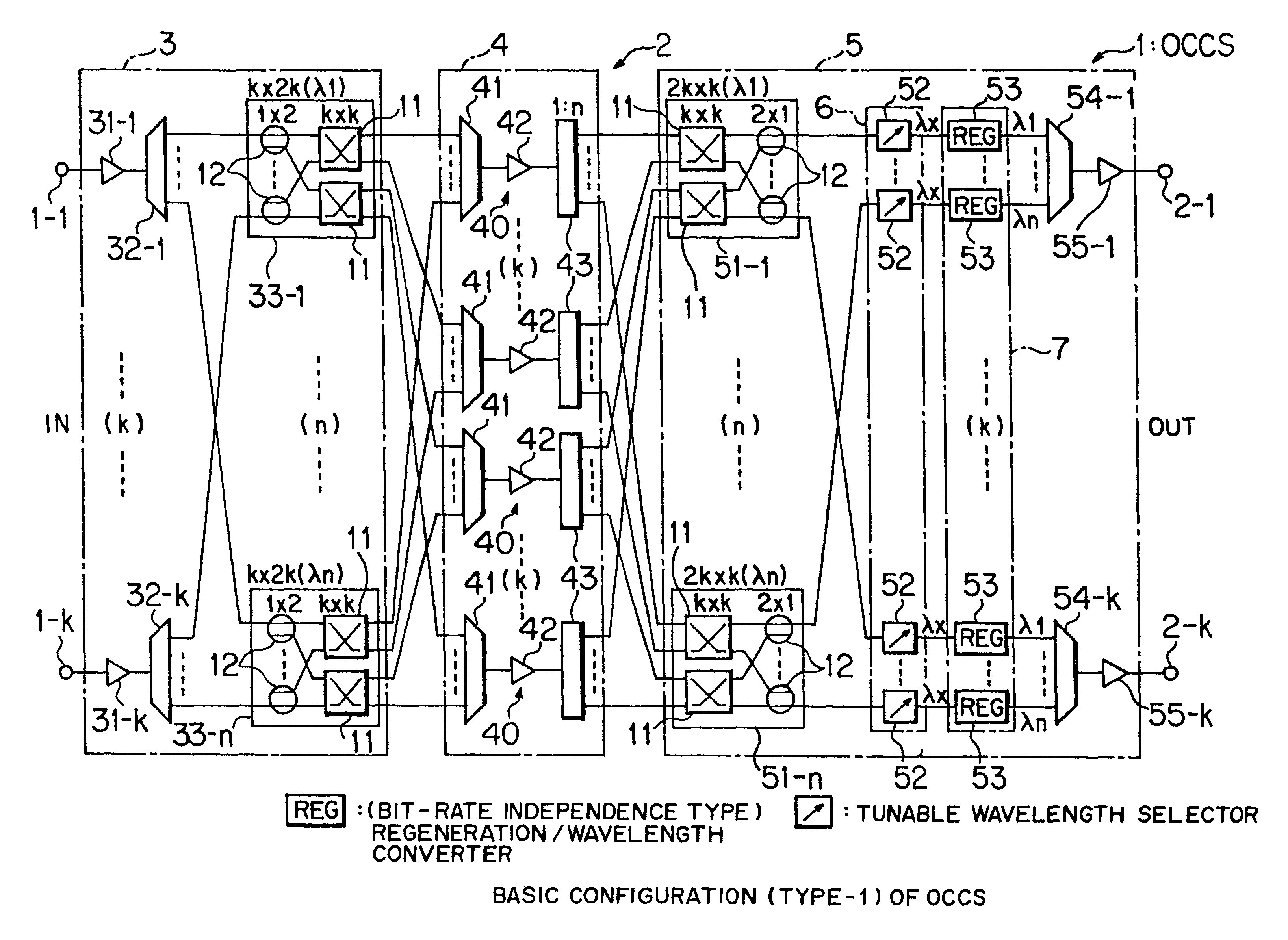
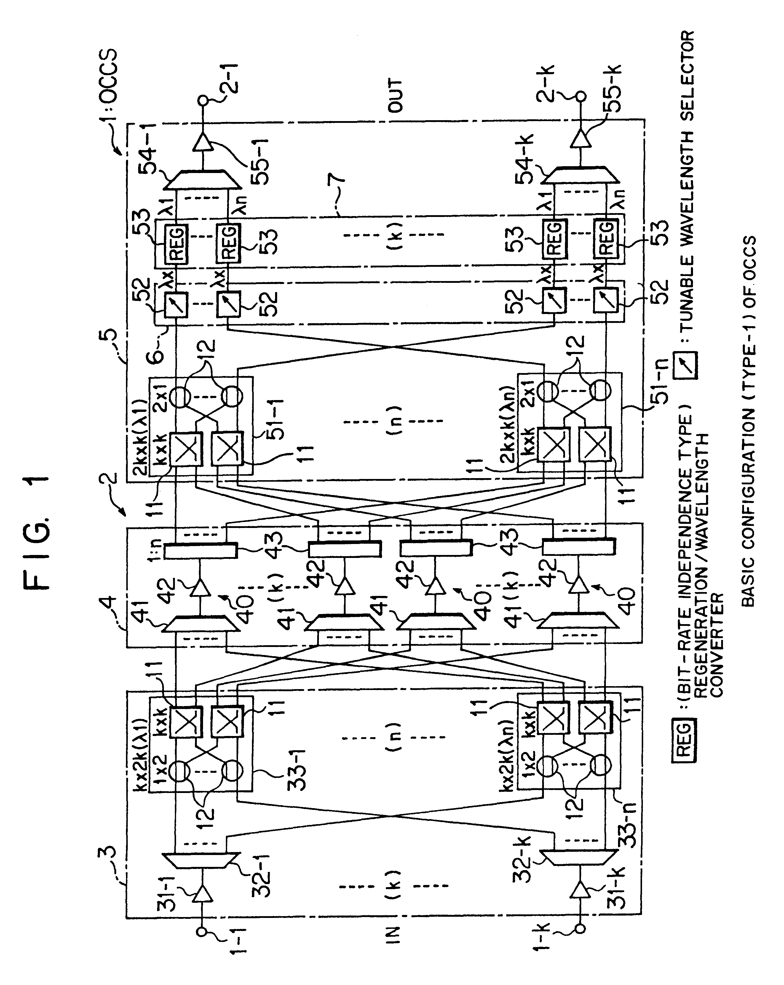
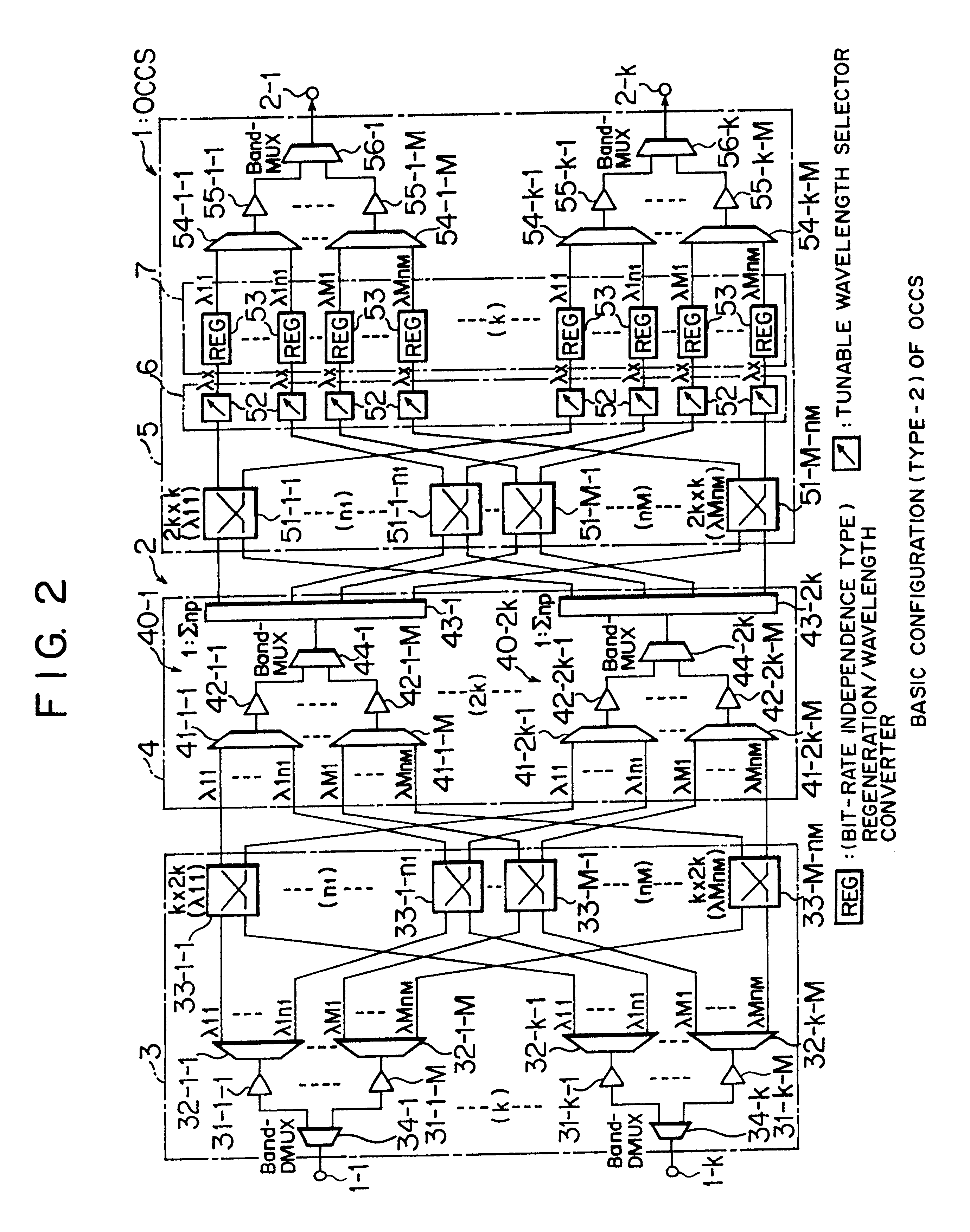
In an optical cross connect apparatus, an optical multiplexing/distributing section wavelength-multiplexes optical signals of wavelengths after routing by an optical input switch section and distributively outputs the resultant multiplexed optical signal as input optical signals to an optical output switch section. In addition, an optical wavelength selecting section conducts wavelength selection processing so that, of the resultant multiplexed optical signal, an optical signal of a desired wavelength is outputted to an output port. With this configuration, it is possible to economically offer an optical cross connect apparatus having an excellent extensibility on a change (particularly, an increase) of the number of wavelengths to be accommodated per port.

Description

(1) Field of the InventionThe present invention relates to an optical cross connect apparatus or system and an optical network, to which the WDM (Wavelength Division Multiplex) transmission technique is applicable.(2) Description of the Related ArtSo far, optical communications have principally employed point-to-point TDM (Time Division Multiplex) transmission. However, with the spread of the Internet or the like, the communication traffic volume (information communication volume) is on the explosive increase and an expectation or possibility exists that the information communication volume further increases afterwards; therefore, two approaches, that is, the speed-up of the TDM transmission and the high-density multiplexing in the WDM transmission, have taken place in the recent years.Of these, the WDM transmission is expected as a technique to increase the communication volume without gaining the signal rate by utilizing the optical broadband characteristics effectively. The WDM t...

Claims


Application Information

Patent Timeline
IPC IPC(8): H04Q11/00H04J14/00H04B10/2507H04B10/27H04B10/272H04B10/299H04J3/00H04J3/04H04J14/02H04Q3/52
CPCH04Q11/0005H04Q2011/0009H04Q2011/0011H04Q2011/0049H04Q2011/0024H04Q2011/0047H04Q2011/0016
Inventor TSUYAMA, ISAONAKAJIMA, ICHIROKUROYANAGI, SATOSHI
Owner FUJITSU LTD
Why Eureka
Try Eureka