Metal-air fuel cell battery system having means for bi-directionally transporting metal-fuel tape and managing metal-fuel available therealong

a fuel cell battery and metal-fuel tape technology, which is applied in the direction of primary cell maintenance/service, cell components, secondary cell maintenance/maintenance, etc., can solve the problems of unfavorable commercialization of rechargeable fcb systems, metal-fuel is not consumed in a uniform manner along the length of the tape structure, and remains unsolved

Inactive Publication Date: 2002-06-25
REVEO
View PDF78 Cites 25 Cited by
  • Summary
  • Abstract
  • Description
  • Claims
  • Application Information

AI Technical Summary

Benefits of technology

Accordingly, a primary object of the present invention is to provide an improved method of and apparatus for electrochemically discharging and / or recharging metal-air fuel cell batteries (FCB) in a manner which avoids the shortcomings and drawbacks of prior art technologies.
Another object of the present invention is to provide such a system, wherein metal-fuel tape can be transported through its discharging head assembly in a bi-directional manner while the availability of metal-fuel therealong is automatically managed in order to improve the performance of the system during the discharging mode of operation.
Another object of the present invention is to provide such a system, wherein metal-fuel tape can be transported through its recharging head assembly in a bi-directional manner while the presence of metal-oxide therealong is automatically managed in order to improve the performance of the system during the recharging mode of operation.

Problems solved by technology

In practice, however, a number of important problems have remained unsolved which have hitherto rendered rechargeable FCB systems commercially unfeasible.
In practice, however, metal-fuel is not consumed in a uniform manner along the length of the tape structure by virtue of the fact that electrical loading conditions vary during tape transport and discharging operations.
Consequently, when using the FCB system design disclosed in U.S. Pat. No. 5,250,370, substantial amounts of metal-fuel will be left abandoned along the length of transported metal-fuel tape during discharging operations.
This results in inefficient use of metal-fuel required during discharging operations, and inefficient use of electrical power required during recharging operations.

Method used


Image

  • Metal-air fuel cell battery system having means for bi-directionally transporting metal-fuel tape and managing metal-fuel available therealong
  • Metal-air fuel cell battery system having means for bi-directionally transporting metal-fuel tape and managing metal-fuel available therealong
  • Metal-air fuel cell battery system having means for bi-directionally transporting metal-fuel tape and managing metal-fuel available therealong

Examples


Embodiment Construction

Of the Present Invention should be read in conjunction with the accompanying Drawings, wherein:

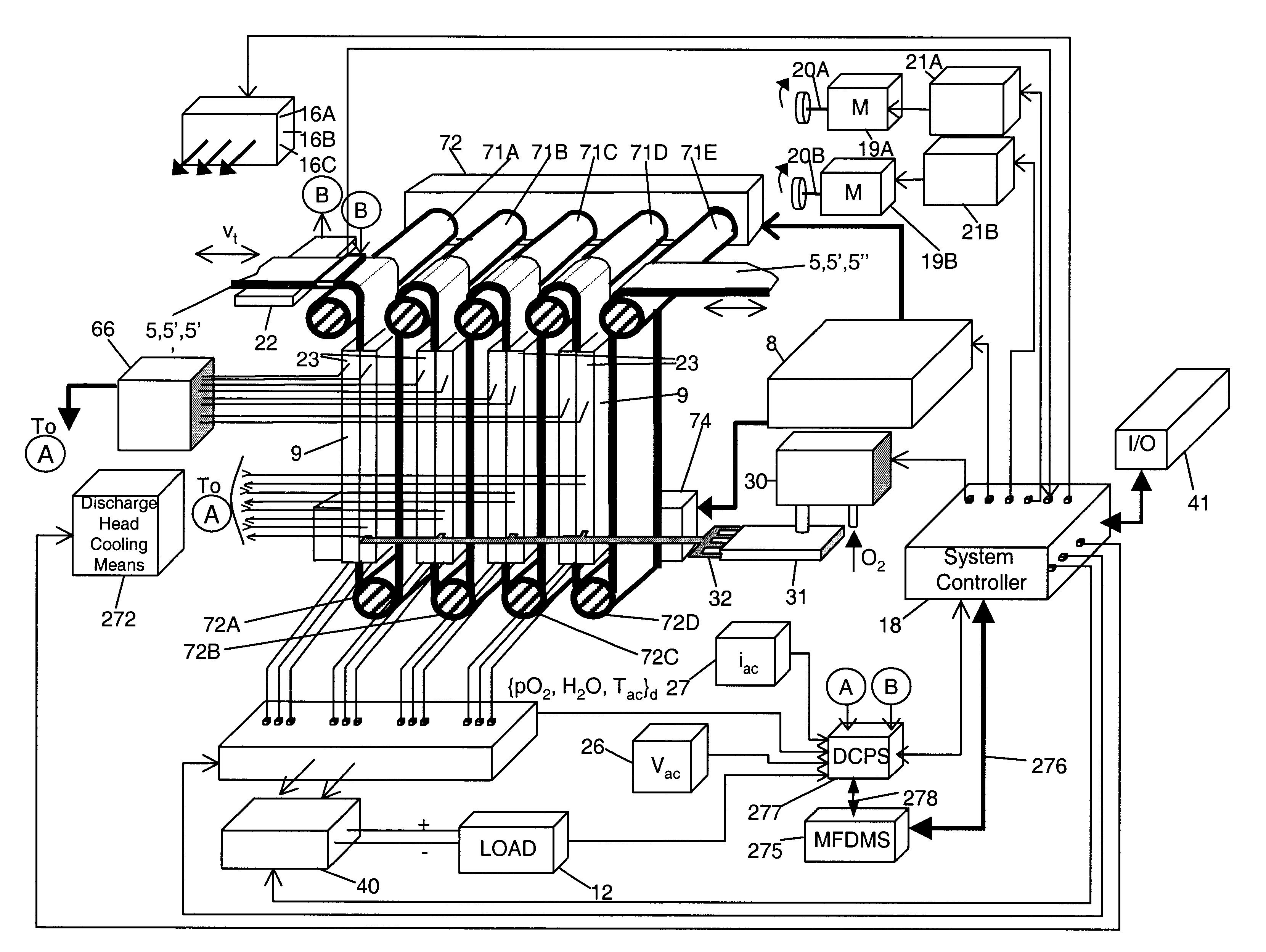
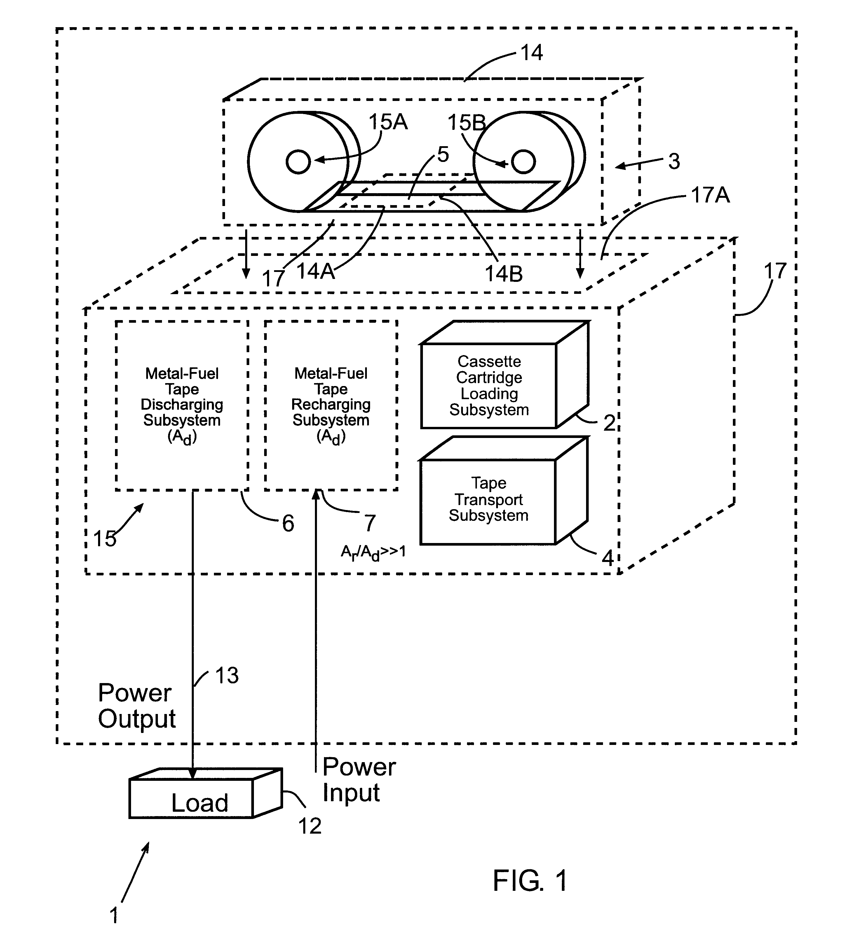
FIG. 1 is a schematic block diagram of a first illustrative embodiment of the metal-air FCB system of the present invention, wherein a Metal-Fuel Tape Discharging Subsystem and a Metal-Fuel Tape Recharging Subsystem are integrated within a single, stand-alone rechargeable power generation unit, and the tape path-length extension mechanism employed in the Metal-Fuel Tape Recharging Subsystem extends oxidized metal-fuel tape over a path-length which is substantially greater than the path-length maintained by the tape path-length extension mechanism in the Metal-Fuel Tape Discharging Subsystem (i.e. A.sub.Recharge >>A.sub.Discharge);

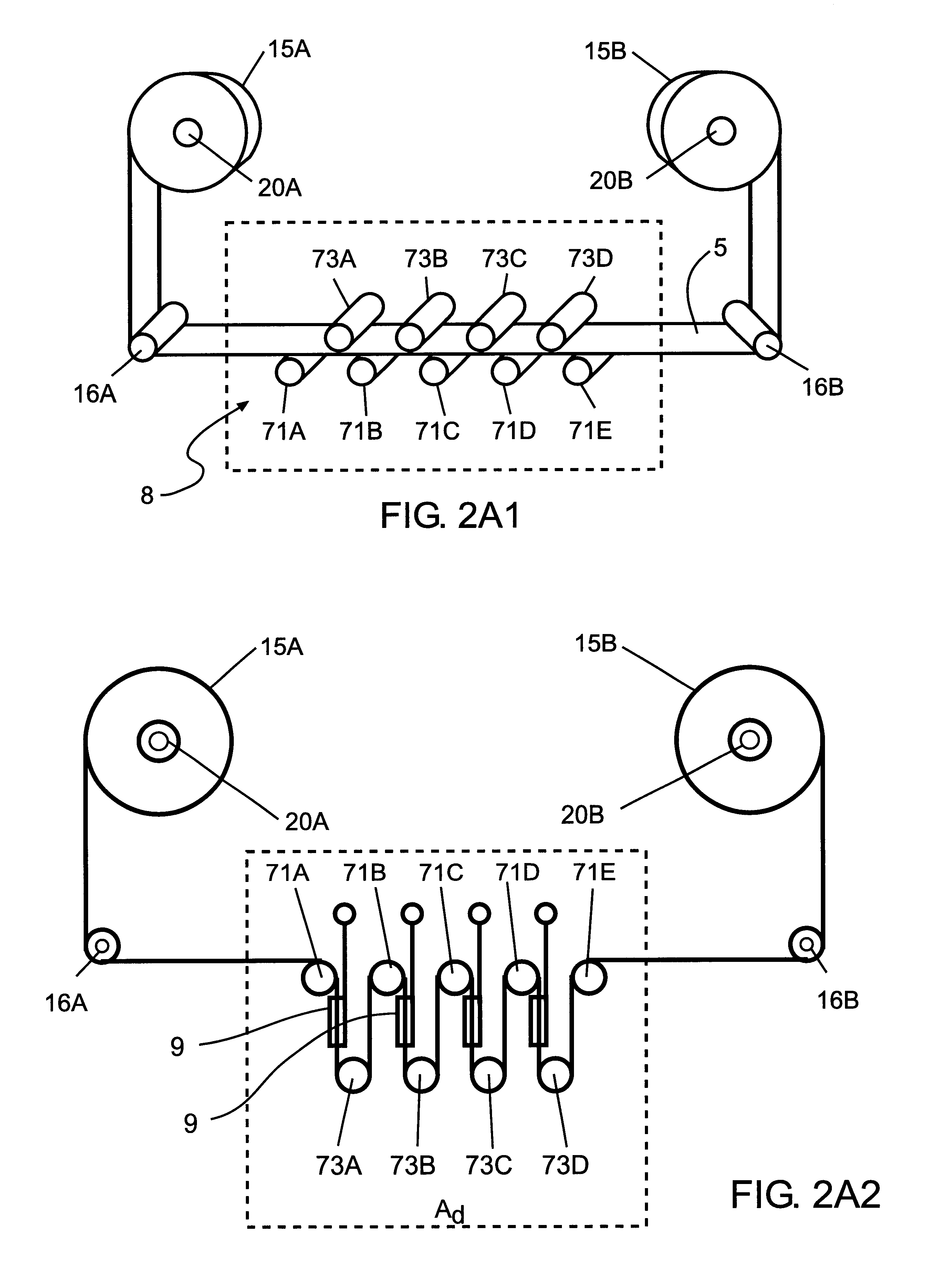
FIG. 2A1 is a generalized schematic representation of the Metal-Fuel Tape Discharging Subsystem of FIG. 1, wherein the tape path-length extension mechanism associated therewith is shown in its non-extended configuration;

FIG. 2A2 is a generalized schematic represen...


PUM

PropertyMeasurementUnit
degree of porosityaaaaaaaaaa
voltageaaaaaaaaaa
output voltagesaaaaaaaaaa

Abstract

Disclosed is a metal-air fuel cell battery system, wherein metal-fuel tape can be transported through its discharging head assembly as well as its recharging head assembly in a bi-directional manner while the availability of metal-fuel therealong is automatically managed in order to improve the performance of the system.

Description

1. Field of the InventionThe present invention relates to an improved way and means of producing electrical power from metal-fuel tape transported through metal-air fuel cell battery (FCB) systems and devices.2. Description of the Prior ArtIn copending U.S. application Ser. No. 08 / 944,507, Applicant discloses several types of novel metal-air fuel cell battery (FCB) systems. During power generation, metal-fuel tape is transported over a stationary cathode structure in the presence of an ionically-conducting medium, such as an electrolyte-impregnated gel. In accordance with well known principles of electro-chemistry, the transported metal-fuel tape is oxidized as electrical power is produced from the system.Metal-air FCB systems of the type disclosed in U.S. application Ser. No. 08 / 944,507 have numerous advantages over prior art electro-chemical discharging devices. For example, one advantage is the generation of electrical power over a range of output voltage levels required by parti...

Claims


Application Information

Patent Timeline
Patent Type & Authority Patents(United States)
IPC IPC(8): H01M12/06H01M12/00H01M8/04H01M2/02H01M2/12H01M4/00H01M4/02H01M4/70H01M10/46H01M10/48
CPCH01M6/5011H01M8/184H01M8/186H01M8/22H01M10/4214H01M12/06H01M12/08H02J7/00H01M4/42H01M2/1673Y02E60/528H01M4/8605H01M10/44H01M2004/024H01M2300/0085H01M50/46Y02E60/10Y02E60/50
Inventor FARIS, SADEG M.
Owner REVEO
Why Eureka
Try Eureka