Voltage source converters operating either as back-to-back stations or as parallel static var compensators

a voltage source converter and back-to-back station technology, applied in the direction of dc-ac conversion without reversal, process and machine control, instruments, etc., can solve the problems of high cost and bulky of the transformer

Inactive Publication Date: 2002-06-25
ABB POWER GRIDS SWITZERLAND AG
View PDF9 Cites 70 Cited by
  • Summary
  • Abstract
  • Description
  • Claims
  • Application Information

AI Technical Summary

Problems solved by technology

However, the series transformer of the UPFC has the full line voltage on both of its si...

Method used


Image

  • Voltage source converters operating either as back-to-back stations or as parallel static var compensators
  • Voltage source converters operating either as back-to-back stations or as parallel static var compensators
  • Voltage source converters operating either as back-to-back stations or as parallel static var compensators

Examples


Embodiment Construction

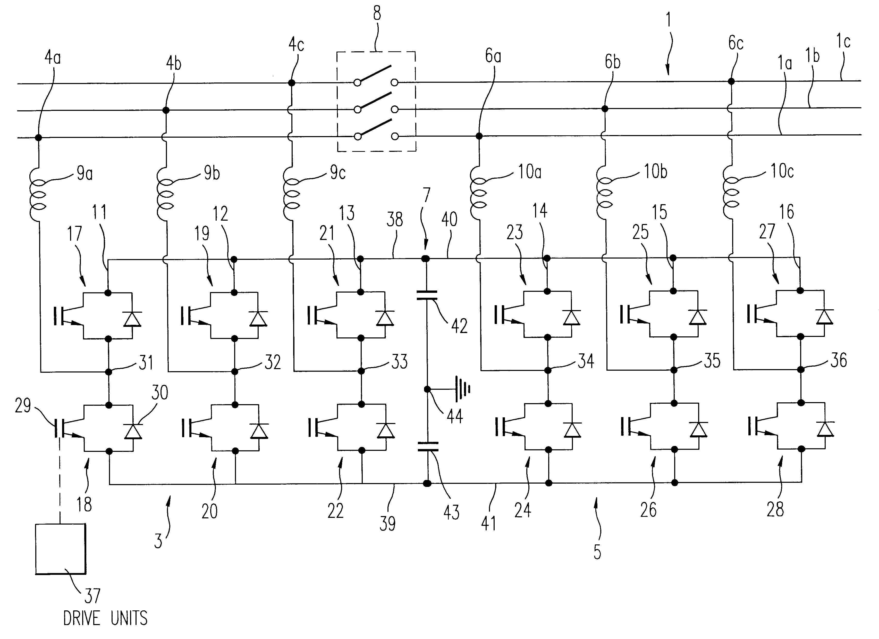
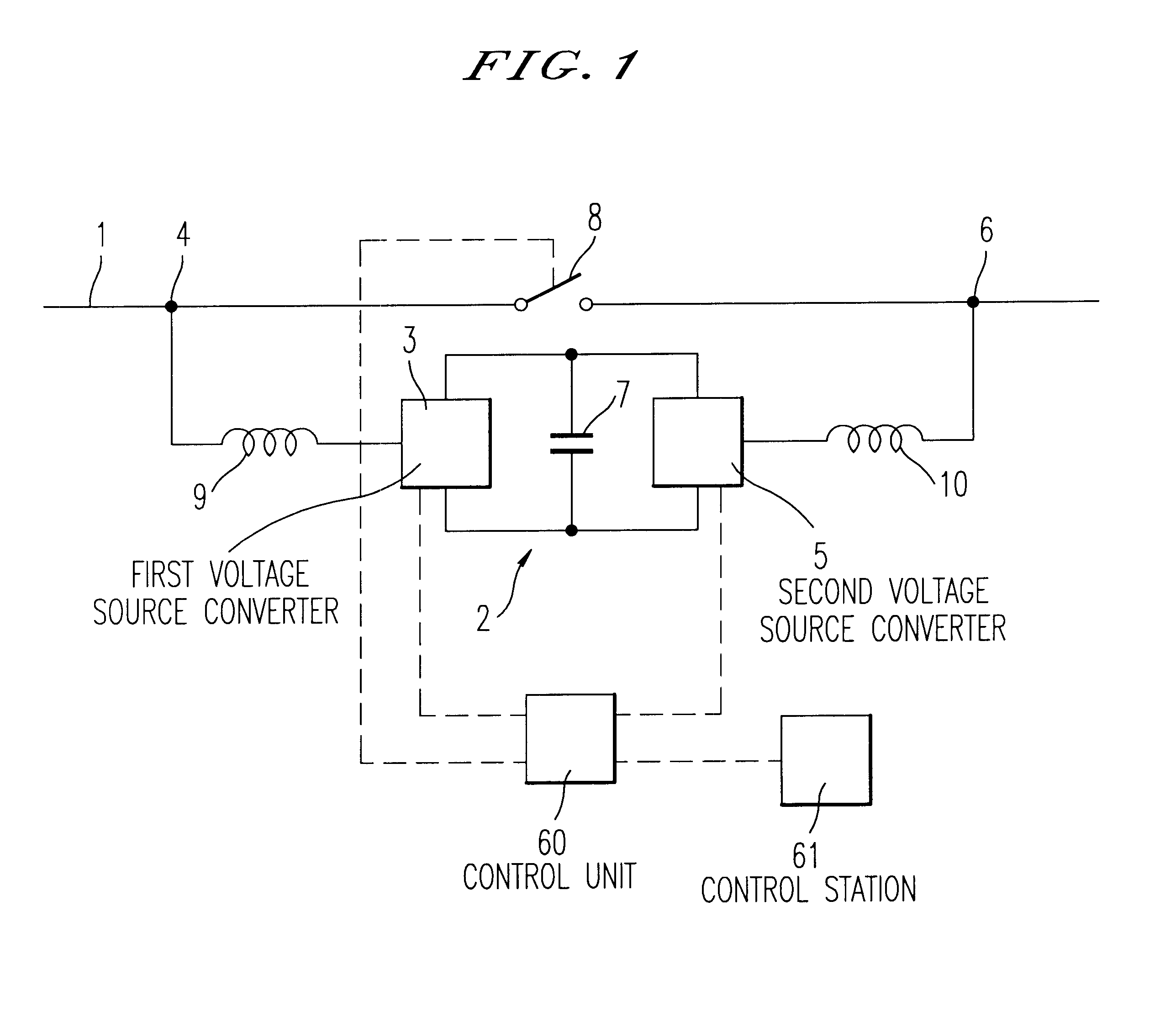
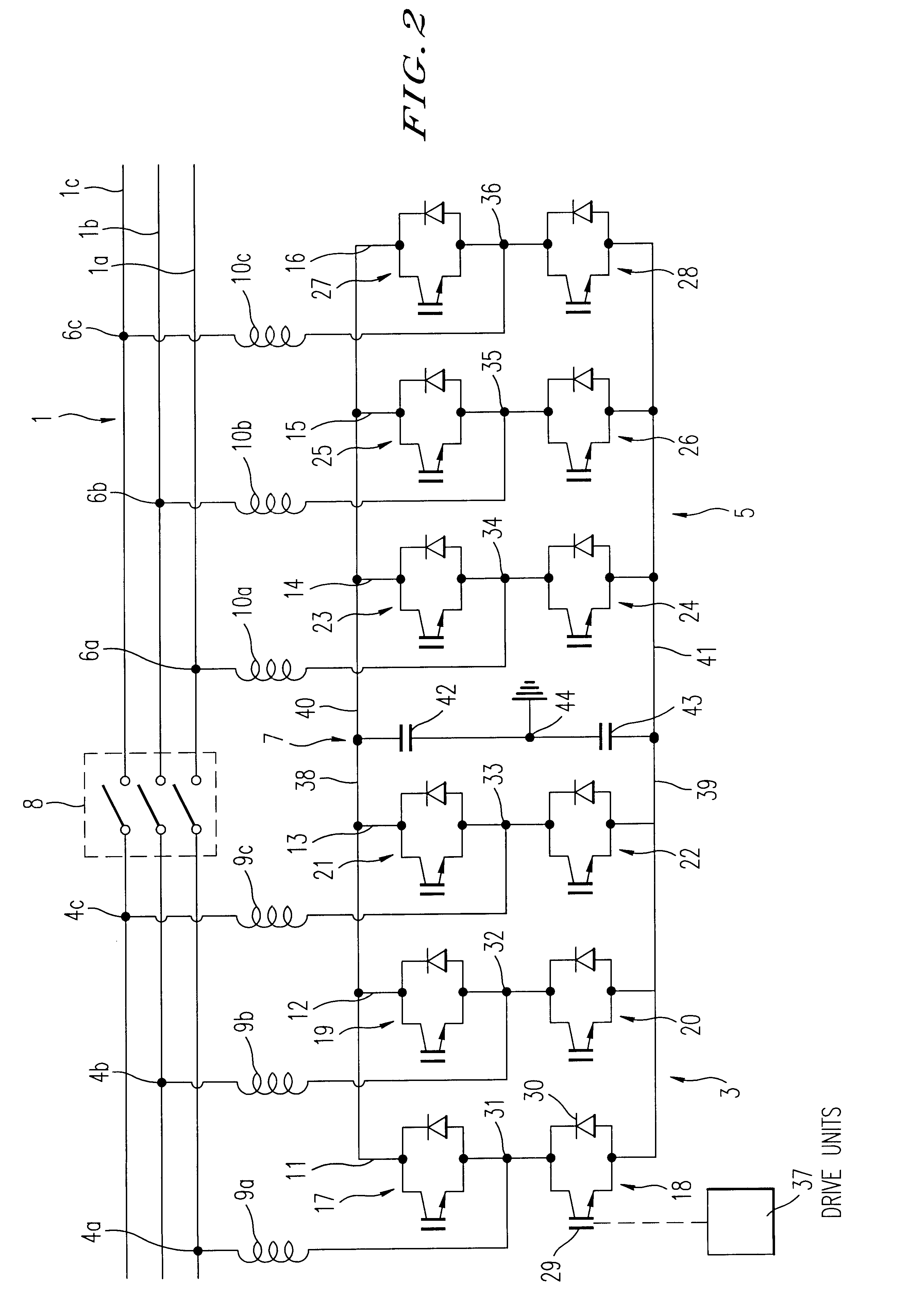
In FIG. 1 the construction of a device according to the invention is schematically illustrated a single line diagram. A transmission line for carrying alternating current and having one or several phases is denoted as 1. A device for controlling the flow of electric power in this transmission line 1 is denoted as 2. This device 2 comprises a first VSC (VSC=Voltage Source Converter), schematically indicated at 3, connected to the transmission line 1 at a first point 4 and a second VSC, schematically indicated at 5, connected to the transmission line 1 at a second point 6, said first and second VSCs 3, 5 having their DC sides connected to a common capacitor unit 7. Furthermore, the device 2 comprises a by-pass switch 8 connected to the transmission line I between said first point 4 and said second point 5 in parallel with the first and second VSCs 3, 5. Each VSC 3, 5 is preferably connected to the transmission line 1 via a phase reactor 9, 10.

The term VSC-converter, i.e. the type of c...


PUM


Abstract

A device and a method for controlling the flow of electric power in a transmission line carrying alternating current, in which a first voltage source converter is connected to the transmission line at a first point and a second voltage source converter is connected to the transmission line at a second point. Further, the first and second voltage source converters have their direct current sides connected to a common capacitor unit. Also included is a by-pass switch connected to the transmission line between the first point and the second point in parallel with the first and second voltage source converters so that the first and second voltage source converters will operate as a back-to-back station when the by-pass switch is open and as two parallel static var compensators when the by-pass switch is closed.

Description

TECHNICAL FIELD OF THE INVENTION AND PRIOR ARTThe present invention relates to a device and a method for controlling the flow of electric power in a transmission line carrying alternating current. The invention also relates to an alternating current network comprising means for controlling the flow of electric power in the network.In an electric transmission system it is of great importance and value to be able to rapidly and precisely control the flow of electric power so as to adapt the power flow to varying load conditions and to achieve a stable and predictable power flow despite disturbances of different kinds. Different types of devices have been proposed and put into operation for achieving this control of power flow. A device commonly used for this purpose is the so-called Unified Power Flow Controller (UPFC). The UPFC consists of two AC / DC voltage source converters designated as exciter and booster, respectively. The DC sides of both converters are connected to a common cap...

Claims


Application Information

Patent Timeline
IPC IPC(8): H02J3/18H02M7/48H02M7/493
CPCH02J3/1814Y02E40/12H02M7/487Y02E40/18Y02E40/10
Inventor BJORKLUND, HANS
Owner ABB POWER GRIDS SWITZERLAND AG
Why Eureka
Try Eureka