
Polarization-adaptive antenna transmit diversity system

a technology of diversity and transmitting antenna, applied in the field of wireless communications, can solve the problems of reducing the strength of the transmitting antenna, affecting the performance of the communication system, and often disturbed electromagnetic waves propagating from the transmitting antenna to the receiving antenna

Inactive Publication Date: 2002-06-25
SKYWORKS SOLUTIONS INC
View PDF17 Cites 190 Cited by
  • Summary
  • Abstract
  • Description
  • Claims
  • Application Information

AI Technical Summary

Problems solved by technology

Unfortunately, ideal conditions are rarely found in the real-world and thus the EM waves that propagate from the transmitting antenna to the receiving antenna are often disturbed by external influences.
These disturbances often reduce the strength of the EM waves that reach the receiving antenna, and thus impair the performance of the communications system.
The impairment caused by signal fading can include reduced range, higher noise, higher error rates, etc.
Fading is usually caused by destructive interference of multipath waves.
However, the strength of the EM wave produced by the transmitting antenna is usually limited by various factors, including, government regulations, the size / cost / weight of the transmitter, the size / cost / weight of the transmitting antenna, and the power available to operate the transmitter.
The waves arriving at the receiving antenna along different paths will often interfere with each other, such that a wave arriving from a first path will tend to cancel a wave arriving from a second path.
Antenna position diversity is rarely used in handheld units because of the size, weight, and cost associated with multiple receiving antennas spaced several wavelengths apart.
This is clearly impractical for a handheld telephone, but very practical for a base station antenna mounted on a large tower.
In some locations, such as Japan, regulatory constraints favor the less effective technique of antenna-switching rather than maximal ratio combining.
If one competitor is allowed to focus EM waves in one direction, then a nearby base station operated by another competitor, and servicing mobile users along the same radiation path, would experience interference.
By reducing the maximum power available to each antenna element in an array of antenna elements, the total power output of the array is limited.
This, unfortunately, greatly reduces the effectiveness of transmit diversity using antenna combining by up to 3 dB for a two-antenna system, and up to 6 dB for a four-antenna system.
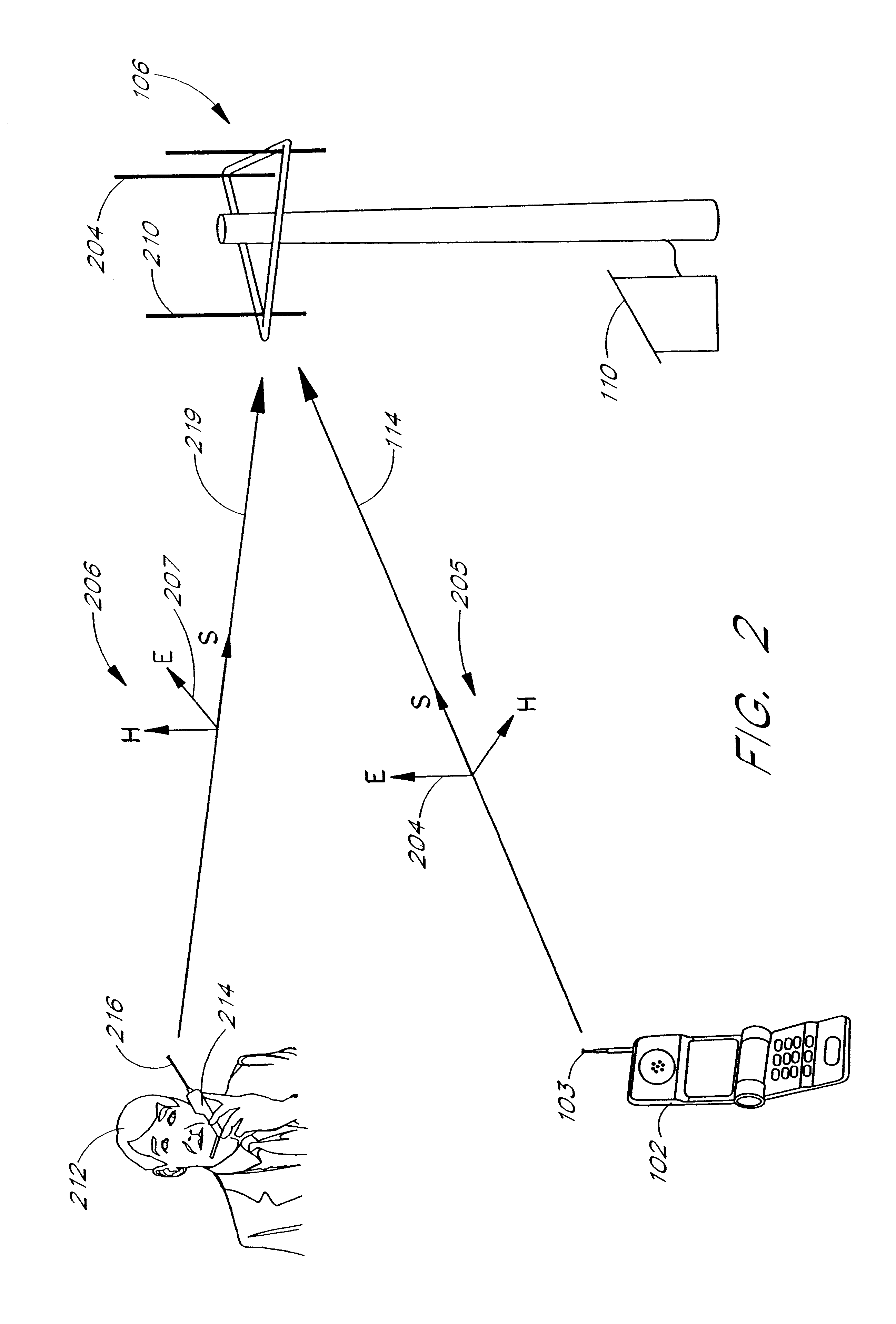
Polarization mismatch fading occurs when the polarization of the EM wave that arrives at the receiving antenna does not match the polarization of the receiving antenna.
For example, polarization mismatch fading is common when using a mobile handset because different users will orient the handset at different angles.
Unfortunately, the wireless handset is rarely held so that the antenna is vertical.
Polarization mismatch fading often occurs when the user orients the handheld unit so that the antenna is not vertical.
This polarization mismatch fading sometimes goes unnoticed because most communication systems are designed with a power budget that provides a large excess power margin.
By holding the antenna at less than optimal orientation, the user is merely unconsciously using up some of the power budget designed into the system.
However, at the far fringe of a reception area, most of the power budget is used up just getting the EM waves from the transmitter to the receiver.
However, this study also found that in complex, non-line-of-sight (e.g., multipath) environments, the difference between the horizontal and vertical polarization signal strengths can be small.
Size, cost, and complexity considerations typically prohibit the incorporation of a circularly polarized antenna into the handset.
Likewise, cost, antenna switching losses, and antenna separation considerations tend to disfavor the incorporation of multiple antennas into the handset.
Unfortunately, in the receive-only context, perceived gains have been seen, but they are not sufficient to justify receive-only diversity in many applications. M. Nakano, T. Satoh, and H. Arai, "Up Link Polarization Diversity and Antenna Gain Measurement of a Hand-Held Terminal", IEEE Antennas and Propagation Society International Symposium, Jun. 18-23 1995, vol.
In particular, Turkmani et al. found that a 45-degree oriented handset induced mismatch losses averaging 6 dB, while using two vertical antennas for receive-only antenna-position diversity.
Although, performance of a communication system can be improved by using a receive-only polarization-diversity, the gains are modest and may not justify the additional cost and complexity of implementation.
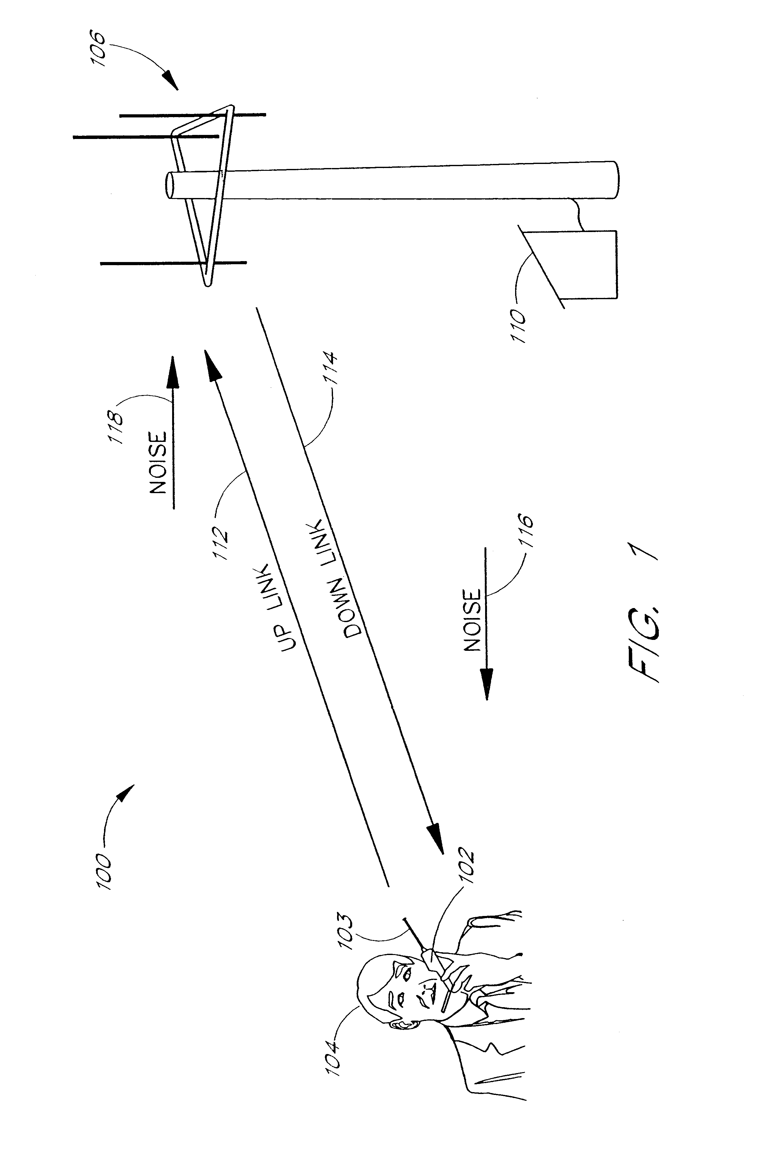
Moreover, implementing receive-only diversity in the base station only improves the communication path from the handset to the base station (the uplink path).
Polarization-diversity in the base station receiving antenna does nothing to improve the communication path from the base station to the handset unit (the downlink path).
In many communications systems, there is little benefit to increasing the uplink performance if downlink performance is not similarly increased, and vice versa.
Unfortunately, as discussed above, implementing antenna diversity in the handset unit is typically not practical due to problems related to cost, weight, size, and complexity.
However, if the noise is loud in relation to the message, the user 104 will have difficulty extracting the message from the noise.
However, a SNR of 0 dB (unity) is often considered to be a practical lower desired limit for real-world systems.
Analog communications systems tend to fail gradually as the SNR drops close to unity.
Unfortunately, government regulations typically limit the strength of the EM wave radiated by the base station 110.
Here again, government regulations often limit the maximum radiated power.
Moreover, other power considerations, such as battery drain, often limit the EM signal strength that can be produced by the handset 102.

Method used


Image

  • Polarization-adaptive antenna transmit diversity system
  • Polarization-adaptive antenna transmit diversity system
  • Polarization-adaptive antenna transmit diversity system

Examples


Embodiment Construction

Although the foregoing has been a description and illustration of specific embodiments of the invention, various modifications and changes can be made thereto by persons skilled in the art.

For example, although described primarily in terms of linear polarization, one skilled in the art will recognize that the present invention can be used with other polarizations, such as, for example, circular polarization, elliptical polarization, etc. The present invention is not limited to wire or loop antennas but may be implemented using any radiating structures or combinations of radiating structures, including, for example, reflector antennas, phased arrays, horns, waveguide apertures, dipoles, dielectric antennas, leaky-wave antennas, inverted F antennas, patch antennas, slot antennas, radiating apertures, spiral antennas, helical antennas, log-periodic antennas, monopoles, etc. Moreover, one skilled in the art will recognize that the term "antenna" as used herein, refers generally to an el...


PUM


Abstract

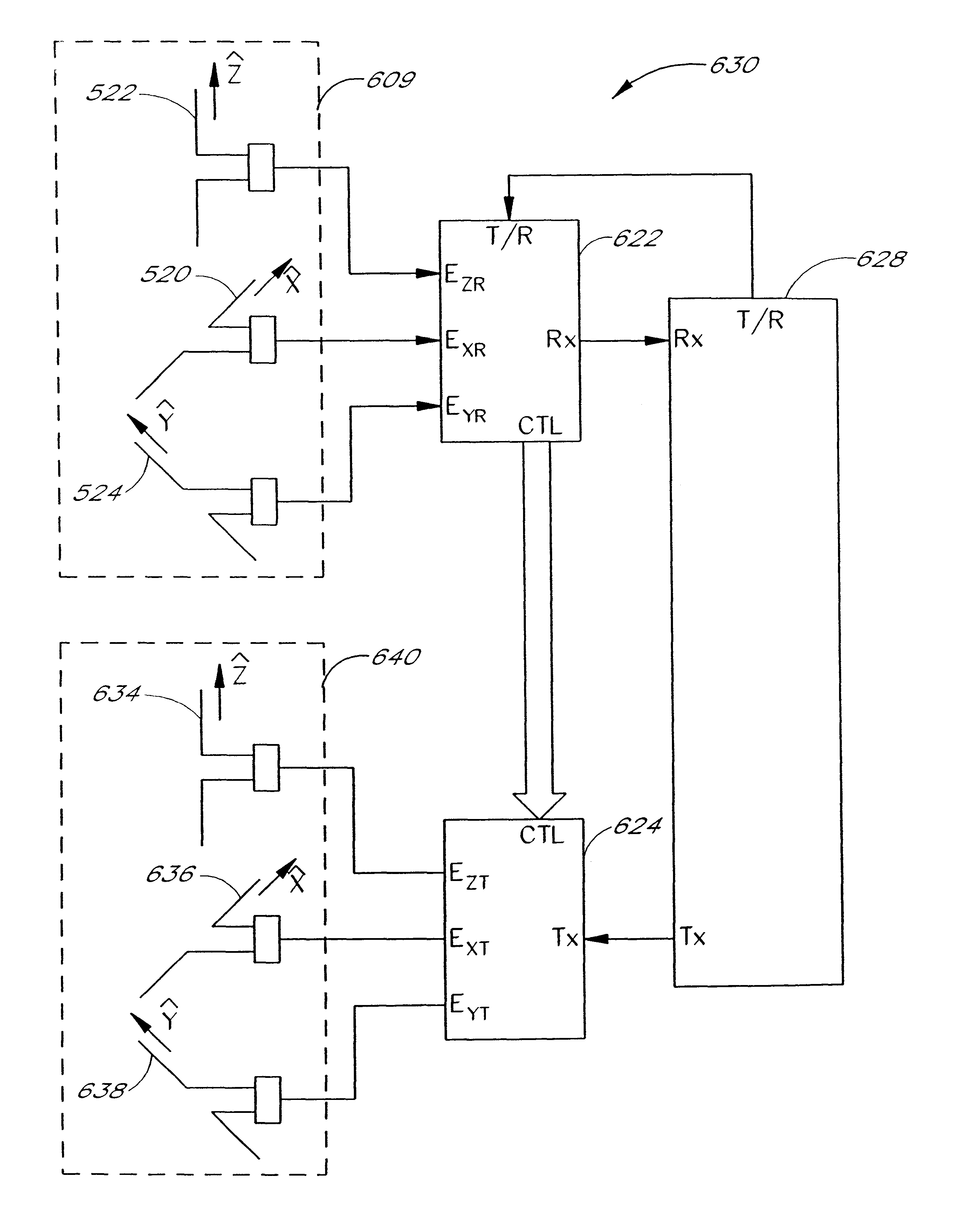
A duplex polarization adaptive system is described. The system provides polarization diversity for base station antennas under both receive and transmitting conditions. Since the base station provides polarization diversity in both transmit and receive modes, no polarization diversity is needed in the handheld unit. Even though the handheld unit does not provide polarization diversity, a duplex communication system, that uses polarization diversity for both the uplink and the downlink is provided, because the base station provides polarization diversity for the uplink and the downlink paths. By installing the two-way diversity at the base station, the overall cost of implementing diversity is reduced because one base station can typically serve many handsets. The base station antenna determines the polarization state of signals received from a remote unit, such as a handheld unit, using a polarization diverse antenna system. The base station then transmits using the same polarization state. The system is compatible with time-division duplex systems.

Description

1. Field of the InventionThe present invention relates to the field of wireless communications, and more particularly, to polarization-diversity systems for wireless communications.2. Description of the Related ArtIt can be fairly said that the age of wireless communications began in 1898 when Guglielmo Marconi broadcast the first paid radio program from the Isle of Wight. The system used by Marconi was a one-way wireless communication system comprising a transmitter that sent messages, carried by electromagnetic waves, to one or more receivers. One-way communications systems, such as broadcast radio, television, etc., are still widely used today.In contrast to one-way systems that can only send messages from one person to another, duplex (two-way) wireless communications systems, such as cellular telephones, cordless telephones, etc., allow two-way communication between two or more parties. In its simplest form, a duplex communication system is the combination of two one-way system...

Claims


Application Information

Patent Timeline
IPC IPC(8): H04B7/10H04B7/02H04B7/08
CPCH04B7/10H04B7/0808H04B7/0857
Inventor EIDSON, DONALD BRIAN
Owner SKYWORKS SOLUTIONS INC
Learn More