Coaxial tilt pin fixture for testing high frequency circuit boards

a translator fixture and high-frequency circuit board technology, applied in the direction of electronic circuit testing, measurement devices, instruments, etc., can solve the problems of limited spacing between spring probe centers in the socket, inability to test high frequency or high-speed uuts, and variations in the character impedance of pins. , to achieve the effect of constant impedance of coaxial pins

Inactive Publication Date: 2002-07-02
DELAWARE CAPITAL FORMATION INC
View PDF24 Cites 16 Cited by
  • Summary
  • Abstract
  • Description
  • Claims
  • Application Information

AI Technical Summary

Benefits of technology

With this embodiment, the top plate is separated from the base plate using two-piece posts. Each two-piece post comprises a first member slidably engaged to a second member. One member is coupled to the top plate and the other member to the base plate. Prior to buckling of the pins, the first member does not span the entire distance between the two plates. A gap exists between the first member and one of the plates. As the two circuit boards are moved toward each other, the pins buckle. Simultaneously, the gap formed between the first member and one of the plates is eliminated. Hence, the initial width of the gap controls the amount of travel between the two circuit boards toward each other, and thus, the amount of bucking of the pins. The spacing between the signal pin and the shield of each coaxial pin remains unchanged even when the coaxial pin is buckled. Consequently, the impedance of the coaxial pins remains constant even when buckled.

Problems solved by technology

The problem with present translator fixtures incorporating pins is that the characteristic impedance of the pins may vary from pin to pin.
As such, current translator fixtures incorporating pins are not suited for testing high frequency or high speed UUTs.
However, because the spacing between spring probe centers in a socket is limited by the physical dimensions of the spring probes, e.g., the spring probe diameter, this type of test setup cannot be used to test UUTs having contact points whose center spacing is relatively short.
Moreover, as the spacing between probes is decreased impedance matching may become infeasible.
It is believed that matched impedance test setups are limited to testing UUTs having contact points whose center spacing is not less than 0.07 inch.
The disadvantage of such fixtures is that they have moving parts which are prone to early failure.

Method used


Image

  • Coaxial tilt pin fixture for testing high frequency circuit boards
  • Coaxial tilt pin fixture for testing high frequency circuit boards
  • Coaxial tilt pin fixture for testing high frequency circuit boards

Examples


Embodiment Construction

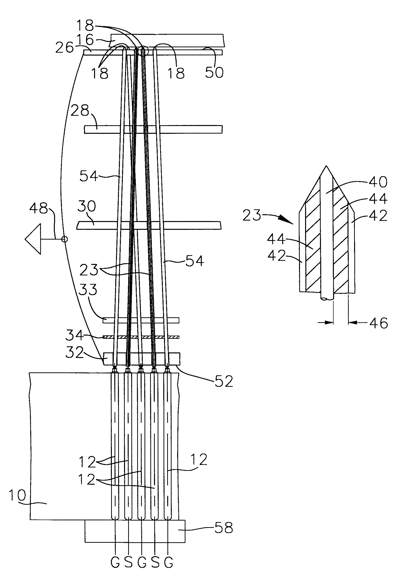
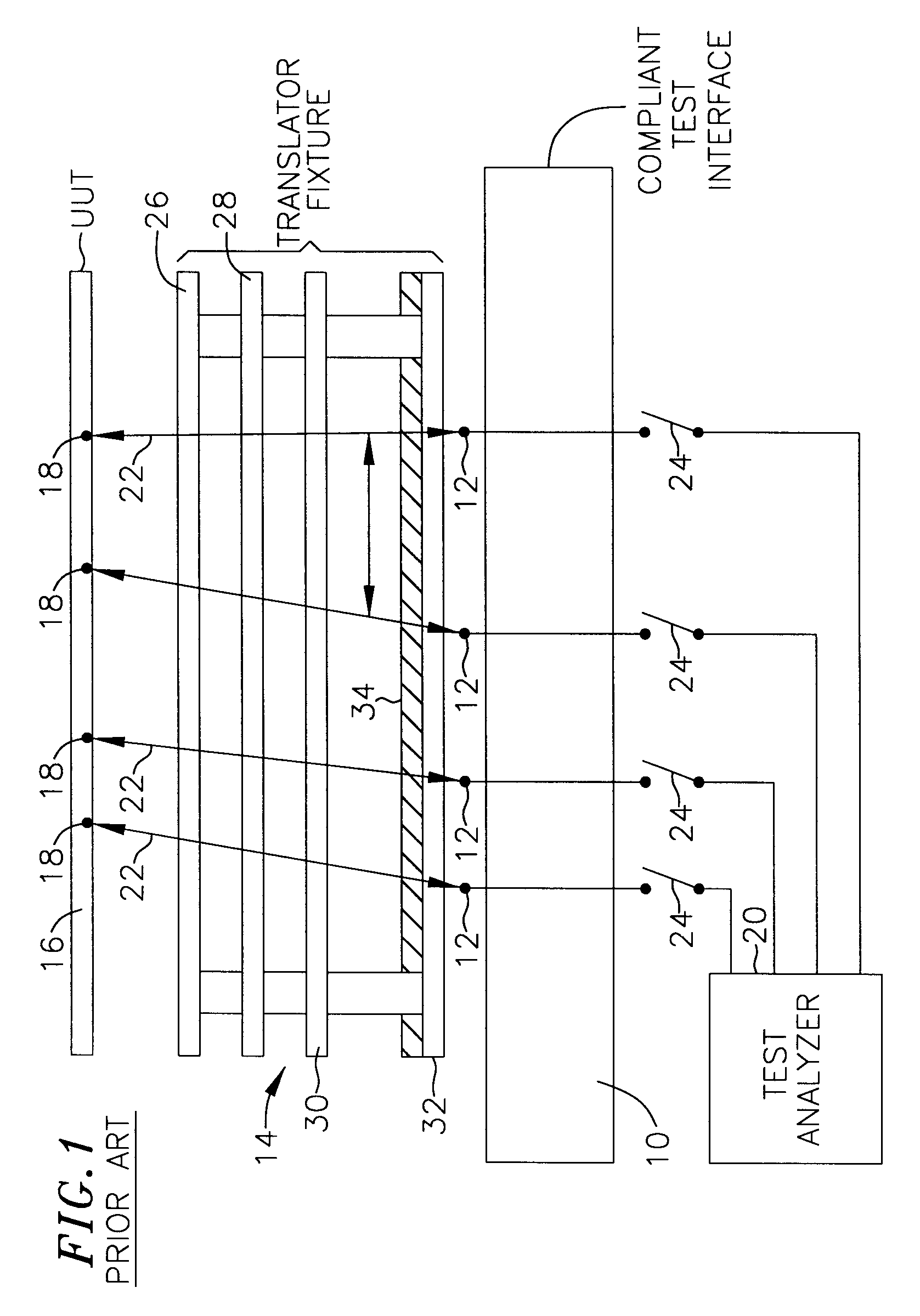
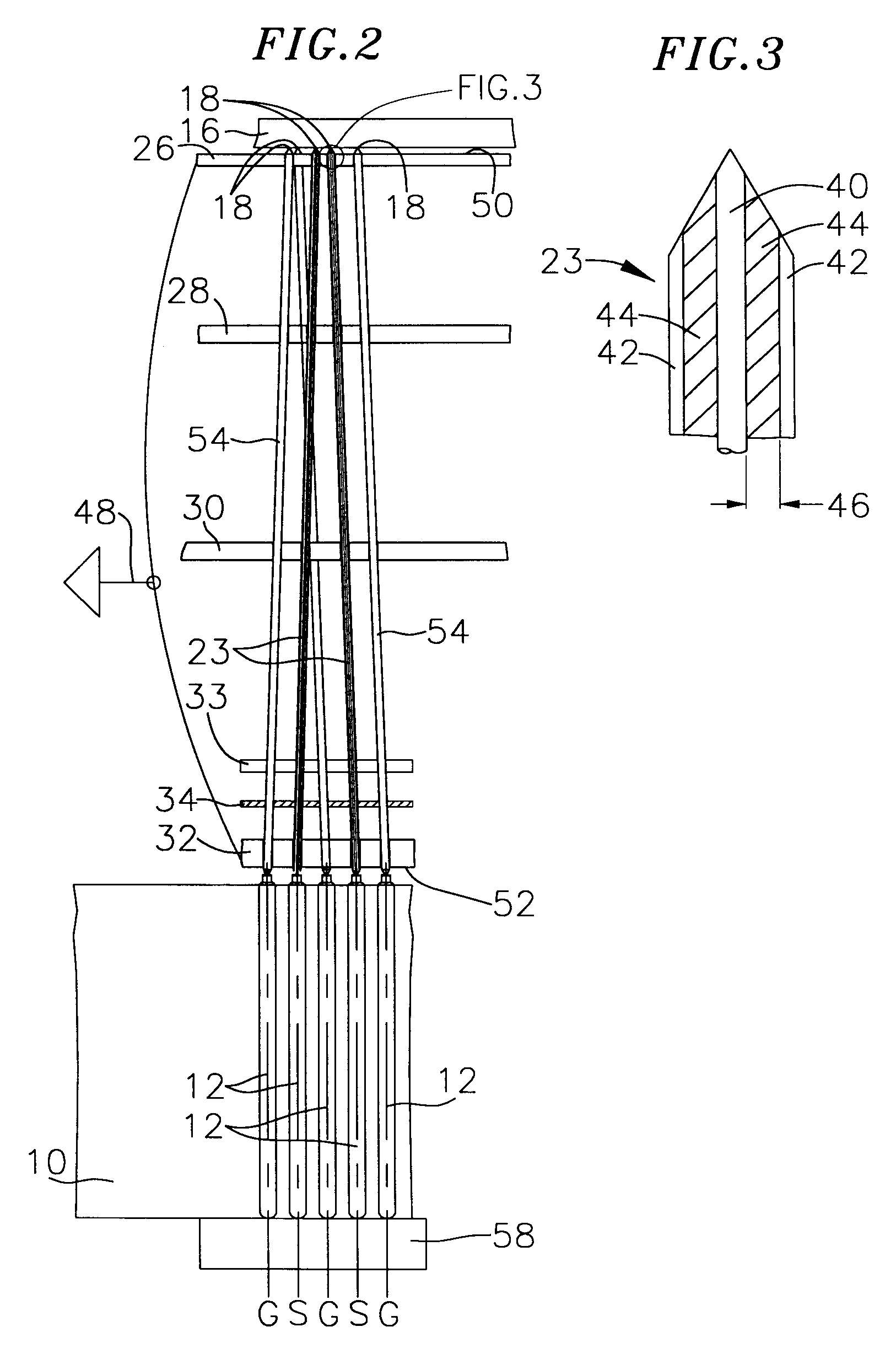
Referring to the schematic block diagram of FIG. 1, a circuit board tester includes a compliant test interface plate or probe field (referred to herein as the "compliant test interface") 10 having an array of spring-loaded test probes 12 arranged on a two-dimensional pattern. This pattern may be a grid pattern consisting of an array of uniformly spaced apart rows and columns of test probes or may be an off-grid pattern, i.e., a pattern that does not consist solely of uniformly spaced apart test probes. The test probes 12 comprise spring-loaded plungers which project above the surface of the compliant test interface, typically uniformly across the array of probes. A translator fixture or interconnect 14 supports a high frequency or high speed printed circuit board 16, or a circuit board with mounted components, or an individual component or grouping of individual components under test (also referred to herein as a "unit under test" or "UUT"). A translator fixture serves as an interfa...


PUM


Abstract

A translator fixture for use in testing high frequency or high speed digital circuit boards. The fixture has a pin supporting top plate and base plate and coaxial constant impedance test pins incorporated into the fixture to provide a signal path from a test analyzer to the circuit board under test. The board under test is coupled to an upper surface of the top plate. The impedance of the coaxial pins is matched to the impedance of the board under test as well as the impedance of the test analyzer. Force exerted on the coaxial pins ensures contact of the pins with test points on the circuit board under test. The force may be exerted by spring loaded probes mounted on a compliant test interface below the base plate. The force may also be exerted by Euler buckling the pins by relative movement between the circuit board under test and a second circuit board coupled to the base plate or to the test analyzer.

Description

FIELD OF THE INVENTIONThis invention relates to the automatic testing of high frequency or high speed printed digital circuit boards and of components mounted on such boards, and more particularly to a matched impedance translator fixture used to translate test signals from a test analyzer to such circuit boards or components.BACKGROUND OF THE INVENTIONAutomatic test equipment for checking printed circuit boards has long involved use of a "bed of nails" test fixture or interconnect in which the circuit board is mounted during testing. This test fixture includes a large number of nail-like spring-loaded test probes arranged to make electrical contact under spring pressure with designated test points on the circuit board under test, also referred to as the unit under test or "UUT." Any particular circuit laid out on a printed circuit board is likely to be different from other circuits, and consequently, the bed of nails arrangement for contacting test points in the board must be custo...

Claims


Application Information

Patent Timeline
Patent Type & Authority Patents(United States)
IPC IPC(8): G01R1/073
CPCG01R1/07357G01R1/06772
Inventor JOHNSTON, CHARLES J.
Owner DELAWARE CAPITAL FORMATION INC
Why Eureka
Try Eureka