Method and apparatus for communicating coded messages in a wellbore

a wellbore and coded message technology, applied in the field of data transmission systems, can solve the problems of reducing or diminishing the operating clearance, unable to meet the expected long service life, and being considered cost-effectiv

Inactive Publication Date: 2002-07-02
BAKER HUGHES INC
View PDF7 Cites 89 Cited by
  • Summary
  • Abstract
  • Description
  • Claims
  • Application Information

AI Technical Summary

Benefits of technology

It is still another objective of the present invention to provide a method and apparatus for communicating coded messages in a wellbore between a transmission node and a reception node, through a fluid column extending therebetween, wherein the coded message is composed of a plurality of message segments, each of which corresponds to the presence or absence of a rapid rate of change of the pressure amplitude within the fluid column, wherein filters are utilized to eliminate the influence of pressure changes which fall below or above predetermined rate thresholds.
It is still another objective of the present invention to provide a pressure pulse generation apparatus which is utilized to provide rapid changes in pressure which are detectable at remote locations within the wellbore, but which does not utilize a large volume of fluid, and which does not substantially change the absolute volume of the fluid within a particular wellbore fluid column which comprises a communication channel.
These and other objectives are achieved as is now described. When characterized broadly as a method, the present invention is directed to a method for communicating coded messages in a wellbore between a transmission node and a reception node, through a fluid column extending therebetween. The method is comprised of a plurality of method steps. A transmission apparatus is provided at the transmission node, which is in communication with the fluid column, for altering pressure of the fluid column to generate a coded message which is composed of either "positive" or "negative" rapid changes in pressure amplitude. A reception apparatus is also provided, but is disposed at the reception node. The reception apparatus includes: (1) a rigid structural component with an exterior surface which is in contact with the fluid column and an interior surface which is not in contact with the fluid column, and (2) a sensor assembly which detects changes in elastic deformation of the rigid structural component, which is also maintained out of contact with the fluid column. The transmission apparatus is utilized to alter pressure of the fluid column in a predetermined pattern to generate at least one coded message. The reception apparatus is utilized to detect the coded message in the fluid column through changes in the elastic deformation of the rigid structural component. In one embodiment, the sensor assembly includes a fluid body in communication with the interior surface of the rigid structural component, but which is not in communication with the fluid column. The fluid body is responsive to changes in the elastic deformation of the rigid structural component. Also, preferably, a pressure sensor is provided for directly sensing pressure changes in the fluid body to detect elastic deformation of the rigid structural component. In the alternative embodiment, a strain gage bridge may be utilized to detect elastic deformation of the rigid structural component. In the described embodiments of the present invention, the rigid structural component comprises a mandrel member which at least partially defines the central bore to the wellbore tubular member. The mandrel member is a substantially imperforate component which contains very few, if any, potential fluid leak paths, thus allowing the present invention to be utilized in wellbore completions which are intended for extremely long service lives.
In the preferred embodiment of the present invention, an electromagnetic programming interface is provided which is in electrical communication with the processor. The processor is programmed to provide a particular output in response to the receipt of particular electrical signals from the reception apparatus through an electromagnetic signal received by the electromagnetic program interface. This allows the processor to be programmed without having any direct electrical connection, thus eliminating a potential leak path.

Problems solved by technology

Experience has revealed that data transmission systems which require the utilization of electrical conductors extending between communication nodes in a wellbore are advantageous when data must be communicated within the wellbore at extremely fast transmission rates, or when large blocks of data need to be transferred between communication nodes; however, the utilization of electrical conductors has several serious disadvantages including: (1) since most wellbores include regions which are exposed to corrosive fluids and high temperatures, a long service life cannot be expected from a data transmission system which utilizes electrical conductors; (2) since most wellbores extend for substantial distances, data transmission systems which utilize electrical conductors are not generally considered to be cost effective, particularly when such systems are utilized only infrequently, or in a limited manner; (3) since all wellbores define fairly tight operating clearances, utilization of a wireline conductor to transmit data may reduce or diminish the operating clearance through which other wellbore operations are performed; and (4) since wellbores typically utilize a plurality of threaded tubular members to make up tubular strings, utilization of an electrical conductor to transmit data within the wellbore complicates the make-up and break-up of the tubular string during conventional operations.
To date, no entirely satisfactory data transmission system has been developed for utilization in completion operations, nor has a satisfactory data transmission system been developed for utilization during prolonged production periods.

Method used


Image

  • Method and apparatus for communicating coded messages in a wellbore
  • Method and apparatus for communicating coded messages in a wellbore
  • Method and apparatus for communicating coded messages in a wellbore

Examples


Embodiment Construction

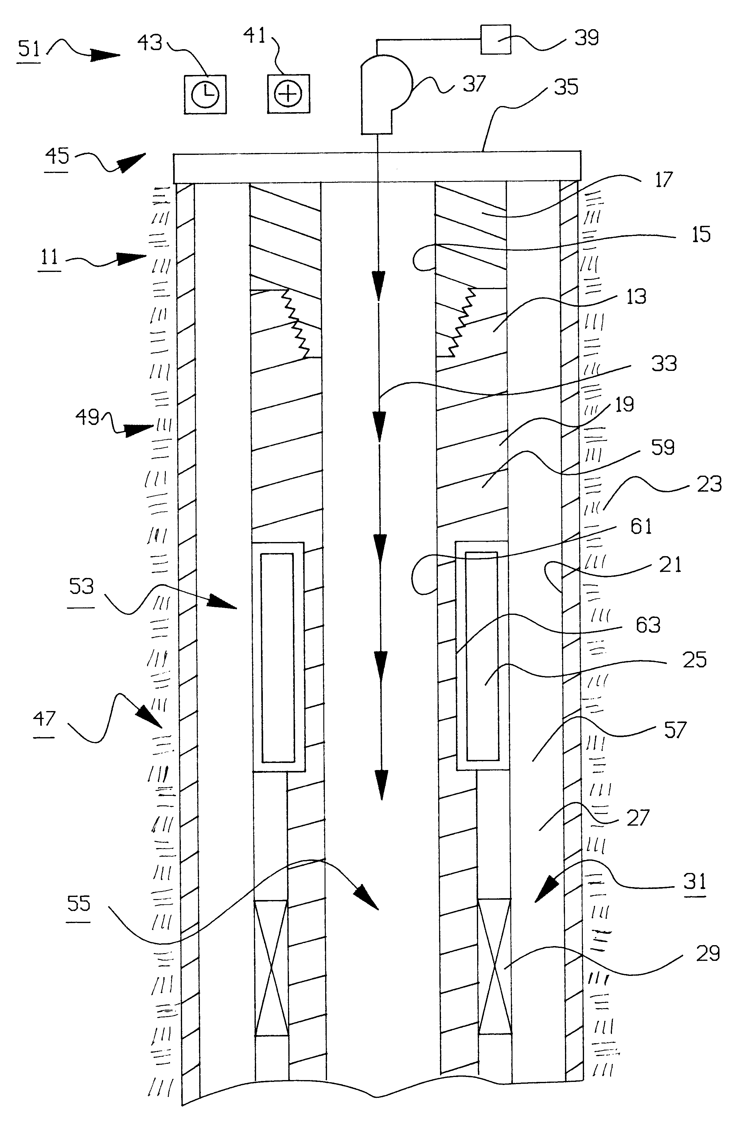
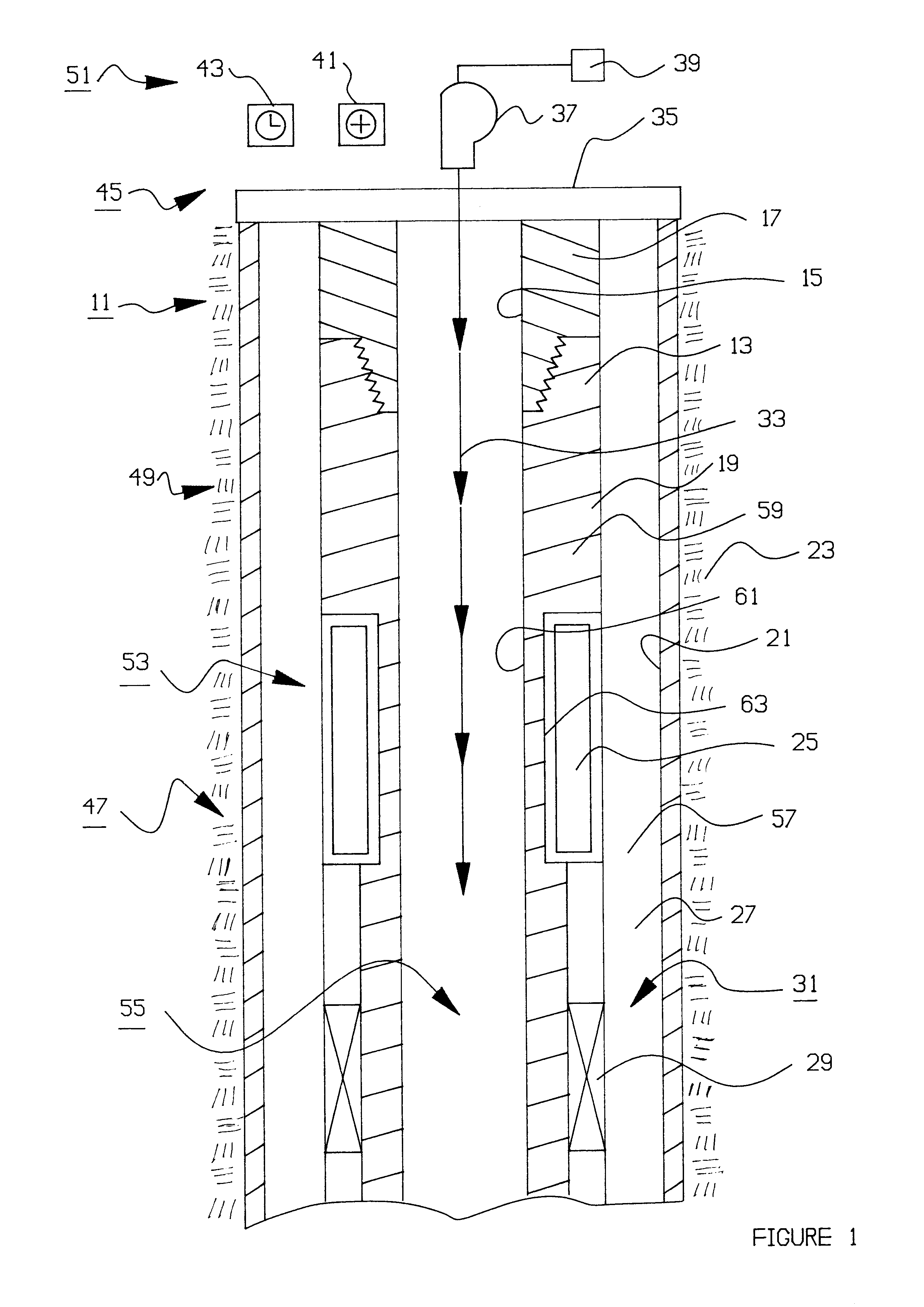
In the present invention, several alternatives are provided. There are alternative techniques for generating a coded message at a transmission node, including: a "negative pulse technique" which utilizes a conventional fluid pump and a conventional valve to generate a plurality of "negative" pressure pulses which constitute a coded message, and a "positive pulse technique" which utilizes a unique valving apparatus to generate a plurality of "positive" pressure pulses which constitute a coded message.

There are also alternative techniques for sensing the coded message at a remotely located reception node, including: a "pressure transducer technique" which utilizes a pressure transducer which is maintained out-of-contact with wellbore fluids but which nonetheless detects the coded message in a wellbore fluid column through changes in elastic deformation of a rigid structural component, and a "strain gage technique" which utilizes a conventional strain gage bridge to detect directly a s...


PUM

PropertyMeasurementUnit
inner diameteraaaaaaaaaa
internal diameteraaaaaaaaaa

Abstract

A method and apparatus for communicating coded messages in a wellbore between a transmission node and a reception node is provided. The coded messages are messages are impressed upon a fluid column which extends between the transmission node and the reception node. A transmission apparatus is provided at the transmission node which is in communication with the fluid column, for altering pressure of the fluid column to generate at least a portion of the coded message. A reception apparatus is provided at the reception node. The reception apparatus includes a rigid structural component with an exterior surface which is in direct contact with fluid column and an interior surface which is not in contact with the fluid column, and a sensor assembly which detects elastic deformation of the rigid structural component. The transmission apparatus is utilized to alter pressure of the fluid column in a predetermined pattern to generate at least one coded message. The reception apparatus is utilized to detect the coded message in the fluid column through changes in elastic deformation of the rigid structural component.

Description

1. Field of the InventionThe present invention relates in general to data transmission systems, and in particular to data transmission systems which may be utilized in wellbores to communicate coded messages through fluid columns disposed therein.2. Description of the Prior ArtIn the oil and gas industry, it has been one longstanding objective to develop data transmission systems which do not require the utilization of electrical conductors to carry coded signals between wellbore locations which are separated by great distances. Experience has revealed that data transmission systems which require the utilization of electrical conductors extending between communication nodes in a wellbore are advantageous when data must be communicated within the wellbore at extremely fast transmission rates, or when large blocks of data need to be transferred between communication nodes; however, the utilization of electrical conductors has several serious disadvantages including: (1) since most wel...

Claims


Application Information

Patent Timeline
Patent Type & Authority Patents(United States)
IPC IPC(8): E21B23/04E21B47/12E21B47/18E21B33/1295E21B33/12E21B23/06E21B23/00E21B34/10E21B34/00E21B34/06E21B43/1185E21B43/11E21B41/00E21B47/06E21B47/00G01L9/00
CPCE21B23/00E21B23/04E21B23/065E21B33/1295E21B34/06E21B34/063E21B34/066E21B34/102E21B41/00E21B43/1185E21B43/11852E21B47/0006E21B47/06E21B47/18E21B47/185E21B47/187G01L9/0002E21B47/007E21B47/22E21B47/24
Inventor OWENS, STEVE C..BOULDIN, BRETT W.ROTHERS, DAVID E.LEHR, DOUGLAS JULIUSHOLCOMBE, MICHAEL WAYNE
Owner BAKER HUGHES INC
Why Eureka
Try Eureka