Computer-to-cylinder type lithographic printing method and apparatus

a technology of lithographic printing and computer, applied in printing, typewriters, printing plates, etc., can solve the problems of high cost and bulky apparatus, common light and heat modes drawbacks, and plate making methods based on laser exposure suffer environmental drawbacks

Inactive Publication Date: 2002-07-09
FUJIFILM HLDG CORP +1
View PDF3 Cites 47 Cited by
  • Summary
  • Abstract
  • Description
  • Claims
  • Application Information

AI Technical Summary

Benefits of technology

The above-described objects of the present invention have been achieved by providing the following computer-to-cylinder type lithographic printing methods and apparatuses.
loading a plate material on a plate cylinder of a printing apparatus;
forming an image, based on image data signal, directly onto the plate material by an inkjet image-recording process comprising ejecting an oil-based ink from a recording head;
heat-fixing the thus formed inkjet image to prepare a printing plate; and

Problems solved by technology

However, such plate making methods based on laser exposure suffer from an environmental drawback caused by the use of alkaline developer needed to remove background areas of the plate material after image exposure.
This drawback is common to the light and heat modes.
Still other plate making methods based on laser exposure are known, which, however, require expensive and bulky apparatus.
In the methods cited above, the printing plate must be manually loaded on the plate cylinder of a lithographic printing apparatus, thus one requires a relatively long time for plate loading, and, in the case of multi-color printing, registration error tends to occur.
However, this method is disadvantageous in that the desired removability of the image (i.e., cleanability) and press life cannot be accomplished at the same time.
Thermal fixing has a serious effect on the press life.
Then, the thermal resistance of the roller material mainly made of rubber is not enough, and the monomer or additives of the rubbery material tend to bleed under such a high temperature.
The thermal fixing after image formation is significant as it governs the press life of the resulting plate image; however, conventional heating means such as lamp or ceramic heater based on thermal emission and radiative heating required a relatively long heating time of, for example, 20 sec at 100.degree. C. to achieve a sufficient press life.
Contents below the cited range tend to cause various problems such as a poor press life of the recorded image, while, with those exceeding the cited range, homogeneous dispersion becomes difficult or the inkjet head tends to choke, hindering a consistent ink ejection.

Method used


Image

  • Computer-to-cylinder type lithographic printing method and apparatus
  • Computer-to-cylinder type lithographic printing method and apparatus
  • Computer-to-cylinder type lithographic printing method and apparatus

Examples


manufacturing example 1

Manufacture of Particulate resin PL-1

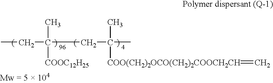
A mixture composed of 10 g of a polymer dispersant (Q-1) having the following formula, 100 g of vinyl acetate and 384 g of Isopar H in nitrogen atmosphere was heated to 70.degree. C. under stirring. The mixture was then added with 0.8 g of 2,2'-azo-bis (isovaleronitrile) (A.I.V.N.) as polymerization initiator, and allowed to react for 3 hr. In 20 min after the addition of the initiator, the mixture turned turbid and the temperature rose to 88.degree. C. After another addition of 0.5 g of the initiator, the mixture was agitated for 2 hr at 100.degree. C. to remove the remaining vinyl acetate. The reaction product was filtered with a 200 mesh nylon cloth after cooling to give a monodisperse, stable latex of 0.23 .mu.m average particle diameter with a polymerization rate of 90%. The particle diameter was measured with CAPA-500, a product of Horiba Seisakusho Co., Ltd. ##STR1##

Part of the latex was centrifuged at 1.times.10.sup.4 r.p.m. for 60 min, a...

example 2a

The printing part of a commercially available solid inkjet printer (Phaser 340J of Sony Techtronix Co.) was used. As in Example 1A, a plate material comprising a 0.12 mm thick aluminum plate the surface of which had been mechanically grained followed by anodic oxidation was loaded on the printing apparatus. After the dust present on the plate material surface was eliminated with air suction using a pump, the ejecting head in which wax ink was kept in a melted state was moved to a position 2 mm apart from the plate material with the help of an optical gap detecting device. Based on the image data to be printed sent to the image data processing and controlling unit, the 64 channel ejecting head, which was moved along with the rotation of the plate cylinder, recorded an image on the aluminum plate with the ejected wax ink. The image formation utilized a 600 dpi bi-level error diffusion halftoning. Image-recording defects or the like due to dust did not take place at all and the dot are...

example 3a

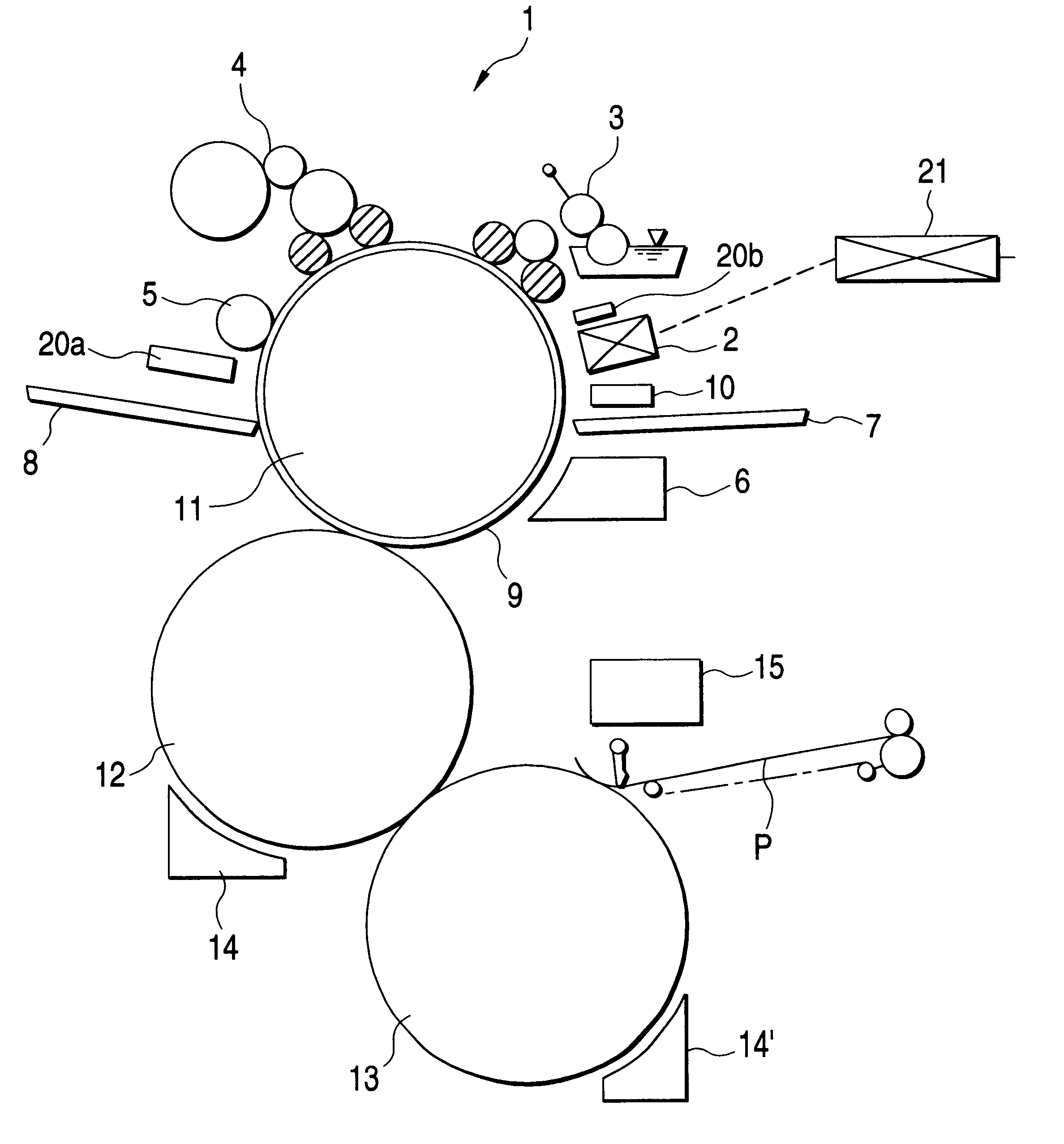
As the inkjet recording device to be installed on each of the four plate cylinders of a single-side, 4 color printing apparatus (See FIG. 9), a 500 channel piezo inkjet printer XaarJet 500S made by Xaar Co. was used that was operated in a share mode. And an oil-based ink or a UV ink, both being products of Xaar Co. With a gap adjusted with a spacing roller made of Teflon, and by sending the image data to be reproduced to the image data processing and controlling unit, image formation on the aluminum plate loaded on each of the four plate cylinders was simultaneously carried out whereby the cylinder was rotated along with the movement of the 500 channel ejecting head. Such a plate making operation was repeated 500 times for each of the oil-based ink and the UV ink. The image resolution was 360 dpi and tone control was done by changing dot size in 8 levels. The image fixing processing was carried out in the same manner as in Example 1A. Image-recording defects due to dust did not take...


PUM


Abstract

A method of computer-to-cylinder type lithographic printing comprising: loading a plate material on a plate cylinder of a printing apparatus; forming an image, based on image data signal, directly onto the plate material by an inkjet image-recording process comprising ejecting an oil-based ink from a recording head; heat-fixing the thus formed inkjet image to prepare a printing plate; and performing lithographic printing with the thus prepared printing plate, wherein said heat fixing step comprises heating with a heat roller. In a preferred embodiment, said heat-fixing step further comprises preliminary heating prior to said heating with the heat roller. Also disclosed are computer-to-cylinder type lithographic printing apparatuses for carrying out the printing methods.

Description

This invention relates to a lithographic printing method based on digital plate making performed on a computer-to-cylinder type printing apparatus, and more specifically, to the method of plate making and printing which is based on the use of an oil-based inkjet ink, achieving an excellent plate image quality as well as an excellent print quality. This invention also relates to a computer-to-cylinder type printing apparatus carrying out such procedures.RELATED ART OF THE INVENTIONIn the conventional lithographic printing, an ink-receptive area and an ink-repulsive area are formed on the surface of a printing plate, and printing ink is fed on the plate so as to selectively adhere to the ink-receptive area. The adhering printing ink is then transferred to paper. Usually, a hydrophilic area and oleophilic (ink-receptive) area are formed on the surface of a printing plate. Then, the hydrophilic area is wetted with fountain solution to repel printing ink.An image formation (plate making)...

Claims


Application Information

Patent Timeline
Patent Type & Authority Patents(United States)
IPC IPC(8): B41J2/01B41J3/407B41C1/10
CPCB41C1/1066B41J2/01B41J3/407B41C1/1075B41P2227/70
Inventor FURUKAWA, KOJIOHSAWA, SADAO
Owner FUJIFILM HLDG CORP
Why Eureka
Try Eureka