High speed linear bagging machine and method of operation

a bagging machine and linear technology, applied in the direction of power operated devices, open-closed containers, packaged goods types, etc., can solve the problems of difficult to synchronize the associated reciprocating bagging device, the bag engagement element is difficult to be engaged, and the scoop position/timing cannot be optimized for different loaf sizes, etc., to achieve high speed, stable condition, and high speed

Inactive Publication Date: 2002-07-23
GLOPAK INC
View PDF10 Cites 44 Cited by
  • Summary
  • Abstract
  • Description
  • Claims
  • Application Information

AI Technical Summary

Benefits of technology

Another feature of the present invention is to provide a high speed linear bagging machine having a reciprocating linear bagger and wherein at least one of the scoops of the bagger is displaceable to positively engage the bag and stretch it with a predetermined pressure and to draw it over the sliced loaf while maintaining the sliced loaf in a s

Problems solved by technology

It is pointed out that all of this known prior art machinery utilized complicated drives and mechanical cams and gears to time and position the components used to bag the bread in a non-stationary scoop type bread bagger.
These designs required frequent mechanical adjustments to the infeed conveyor flights to accommodate different loaf sizes and the scoop position/timing could not be optimized for different loaf sizes.
Furthermore, the infeed conveyor and the discharge conveyor were provided with separate drives and because of their mechanical mechanisms frequent adjustments were necessary to try to synchronize their drives and it became more difficult to then synchronize the associated reciprocating bagger device which either pushed the loaf into the bag or drew the bag over the loaf.
Another disadvantage of prior art machines is that because of their complex drive and mechanical structures, the machines were subjected to vibrations which destabilized the bag engaging mechanism and this made it difficul

Method used


Image

  • High speed linear bagging machine and method of operation
  • High speed linear bagging machine and method of operation
  • High speed linear bagging machine and method of operation

Examples


Embodiment Construction

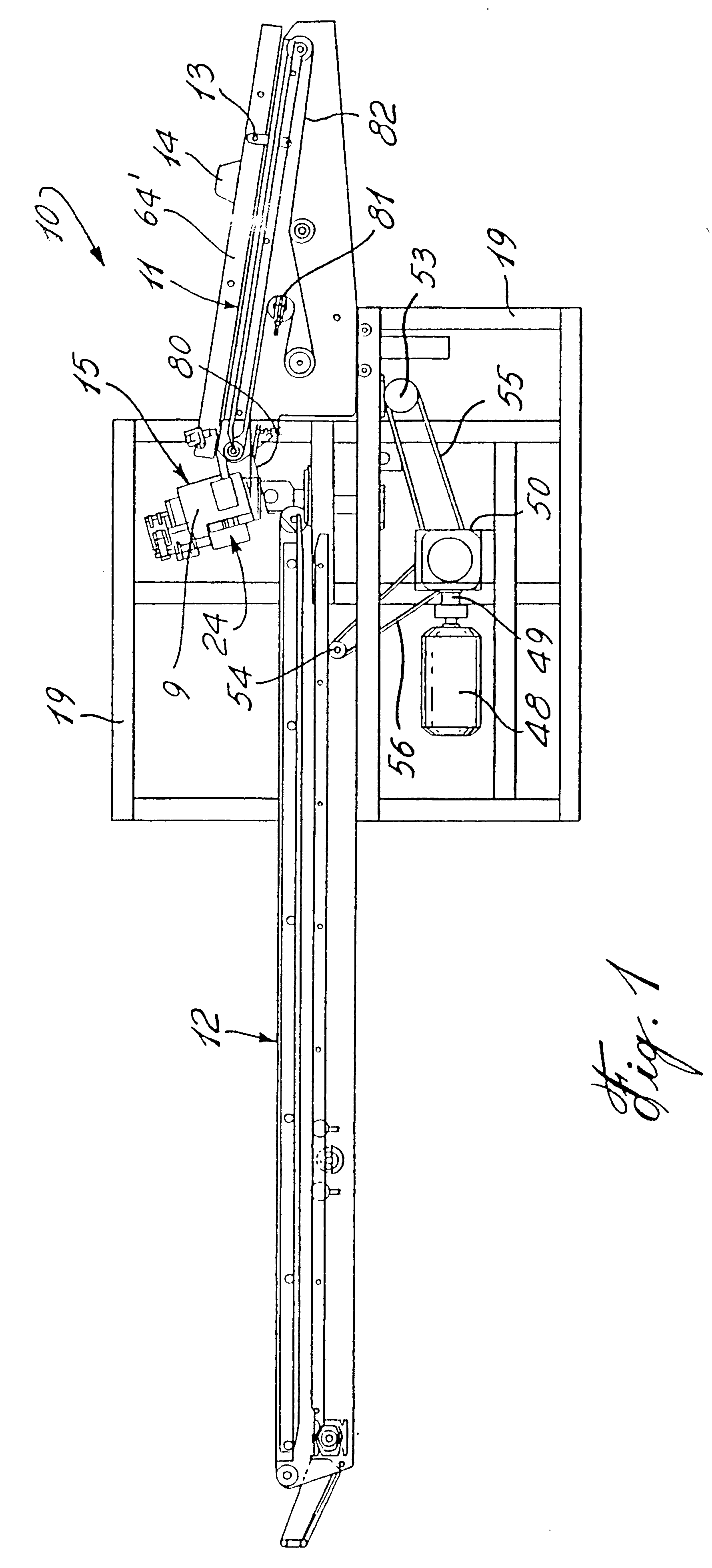
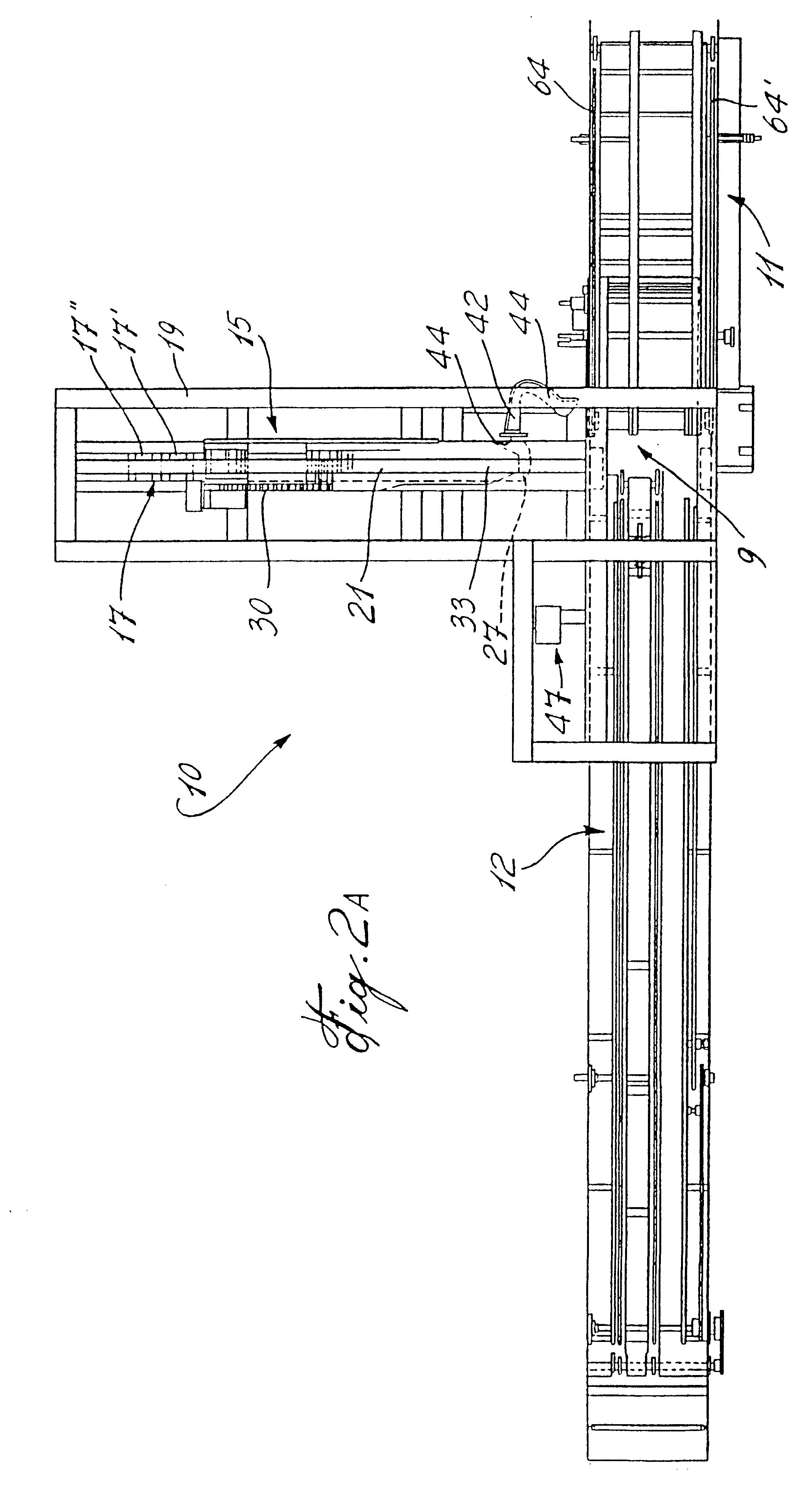
Referring now to the drawings and more particularly to FIGS. 1 and 2, there is shown generally at 10 the high speed linear bagging machine of the present invention and herein including a linear bagger assembly 15, an infeed conveyor 11 and a discharge conveyor 12. The infeed conveyor 11 is provided with pusher rods 13 which convey a product, herein a loaf of sliced bread 14, to a bagging station 9.

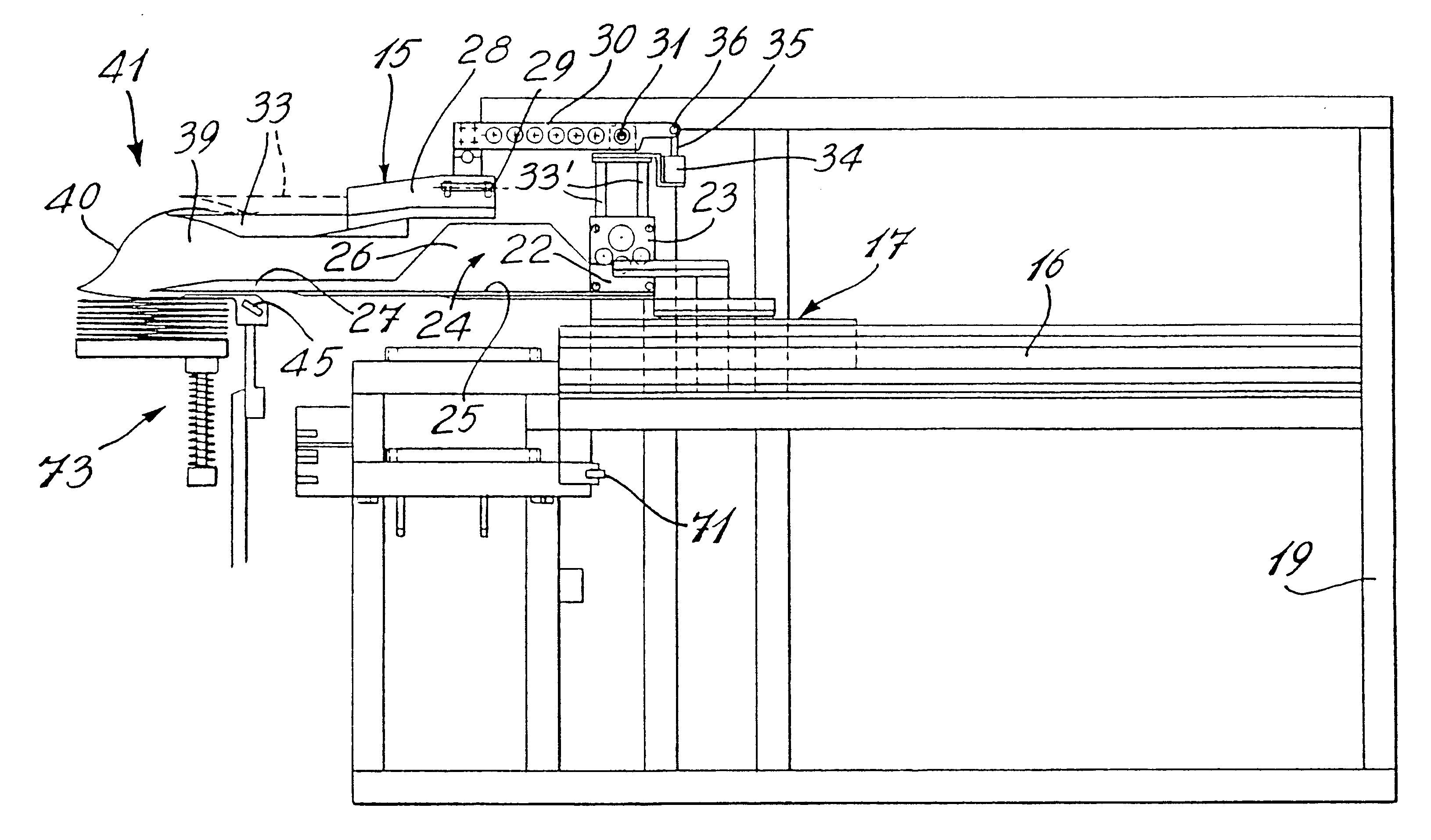
As seen more clearly in FIGS. 2A to 4, the bagging machine 10 comprises a reciprocating linear bagger assembly 15 which is herein displaceable on a straight slide support rod 16. The slide support rod 16 is a magnetic stator of a linear drive device 7. The linear drive device is provided with a thrust block 17 displaceable on the rod 16 by two electric coils 8 and 8' and housed in the housings 17' and 17", thereunder (see FIG. 2B). The thrust block 17 herein constitutes a carriage for the reciprocating linear bagger 15. By controlling the current through one of the coils the carriage is di...


PUM

PropertyMeasurementUnit
Lengthaaaaaaaaaa
Pressureaaaaaaaaaa
Speedaaaaaaaaaa

Abstract

A high speed linear bagging machine and method of bagging a product with such machine is described. The machine has a reciprocating linear bagger assembly which has a straight drive member with a carriage connected thereto. A drive having a pair of coils is used to drive the straight drive member to displace the carriage. A stroke controller is used to control the coils dependent on a desired forward and rearward displacement stroke of a carriage along the drive member. A product receptacle is secured to the carriage and displaceable to a bagging station. A bag engaging member is connected to the carriage and a product arresting member is displaceable for abutting relationship with an end of a product at the bagging station. The bag engaging means engages an open end of a bag at a forward end of the displacement stroke adjacent the bagging station and withdrawing the open end of the bag over the product which is maintained substantially stationary by the product arresting means during a reverse stroke of a carriage whereby to insert the product in the bag and discharge the bagged product. The drive member is comprised of a straight thrust rod of magnetic material which constitutes a stator of the linear motor. The pair of coils are connected to the carriage and energized for displacing the carriage along the thrust rod to cause displacement of the carriage.

Description

The present invention relates to a high speed linear bagging machine and particularly a machine for placing a plastic bag over a sliced loaf of bread.In particular, the present invention is an improvement of PCT Application WO94 / 27867 published on Dec. 8, 1994. The packaging equipment as described in that patent was designed for the automatic packaging of sliced bread in loaf form and wherein the apparatus would operate automatically thereby reducing the labor costs associated with the packaging of sliced bread whilst at the same time reducing labor costs and minimizing contact between laborers and the bread loaf being packaged, this latter advantage being very significant. In particular that machine was concerned with the method of holding a sliced loaf of bread in position and pulling an open bag thereover and then releasing the bag to a bag closing station.Prior to that PCT and as described in U.S. Pat. No. 4,457,124, the machines comprised of delivering loaves of bread to a load...

Claims


Application Information

Patent Timeline
IPC IPC(8): B65B43/26B65B43/34B65B25/16B65B25/00B65B25/18
CPCB65B25/16B65B43/34
Inventor MURGATROYD, JOHNWHITEHILL, W. A.SAVOURY, RICK
Owner GLOPAK INC
Why Eureka
Try Eureka