Clothes drying and dewrinkling cabinet

a drying cabinet and cloth technology, applied in the field of cloth drying and dewrinkling cabinets, can solve the problems of the size of the interior area, the inability to develop a complete and final solution for the household domestic appliance, and the most disagreeable household chores

Inactive Publication Date: 2002-07-30
FAGOR
View PDF6 Cites 37 Cited by
  • Summary
  • Abstract
  • Description
  • Claims
  • Application Information

AI Technical Summary

Benefits of technology

The possibility of opening or closing the airing duct in accordance with the stage the dewrinkling process has reached enables the results to be optimised both at the drying and at the steaming and resting stages. In fact, it is this option of opening or closing the airing duct which makes it possible to combine the drying of wet clothes (clothes taken straight out of the washing machine) and their subsequent dewrinkling in the same cabinet.
Thus, at the initial drying stage (in the case of wet clothes) and at the drying stage after steaming, the airing duct will be kept open so that there is air circulation and moisture is drawn out either to the outside or else to a condensation system provided for this purpose at the output of said airing duct. At the steaming and resting stages, however, said airing duct will be kept closed. In this way, at the steaming stage this will help the clothes to be saturated in steam through preventing the steam from escaping to the exterior. Likewise, at the resting stage the fact of keeping the airing duct closed will assist in stabilising the clothes by preventing air currents to the exterior.
As regards the resting stage, the tests carried out have shown that the introduction of said stage after the steaming stage brings a considerable improvement in the dewrinkling results. In this way, the method of dewrinkling covered by the invention improves on those methods, like that claimed in EP0324589, which introduce the air delivery stage straight after the steaming stage.
Another important feature of the invention is that, as regards the steam supply methods, the steam diffuser is eliminated. The steam is supplied through a duct communicating the tank in which the steam is generated, which is located below the inner area of the cabinet, directly with said inner area. The steam may either be generated in this way or else by supplying air at the same time, so that said air assists in the even distribution of the steam. In this way, the steam supply means are simplified considerably and optimal results are obtained. This design, much simpler for instance than that proposed in EP0324589, makes volume production of the cabinet much more feasible.
On the other hand, a common problem in cabinets of this type is condensation. Tests performed have shown that the cabinet that is the object of the present invention gives no problems of this type. A factor that contributes to this is, together with the use of a thermally insulating material for the forming of the cabinet, the fact that the steam is supplied to the inner area by way of a duct that communicates the steam generating tank and said inner area directly, so that said steam does not undergo any loss of energy in reaching said inner area.

Problems solved by technology

It is a proven fact that one of the most disagreeable household chores is the process that starts off when clean clothes (garments, sheets, etc.) are taken out of the washing machine and finishes when they are stowed away in the respective wardrobe duly ironed (hanging the washing taken out of the washing machine, bringing it in when dry, organizing the ironing thereof, etc.).
There have been many attempts to expedite and simplify this process, but no household domestic appliance has been developed to date offering a complete and final solution.
Clothes drying cabinets are well known, but they only offer a partial solution to the task that starts after the washing has been done, its main contribution being the speeding-up of the drying process.
Lastly, the size of the interior area of the EP0324589 cabinet is not the most suited either for the ends pursued (facilitating the operations that begin after the clothes are washed and conclude after their ironing), as said cabinet does not have sufficient capacity to hold the clothes corresponding to a wash.
On the other hand, a common problem in cabinets of this type is condensation.

Method used


Image

  • Clothes drying and dewrinkling cabinet
  • Clothes drying and dewrinkling cabinet
  • Clothes drying and dewrinkling cabinet

Examples


Embodiment Construction

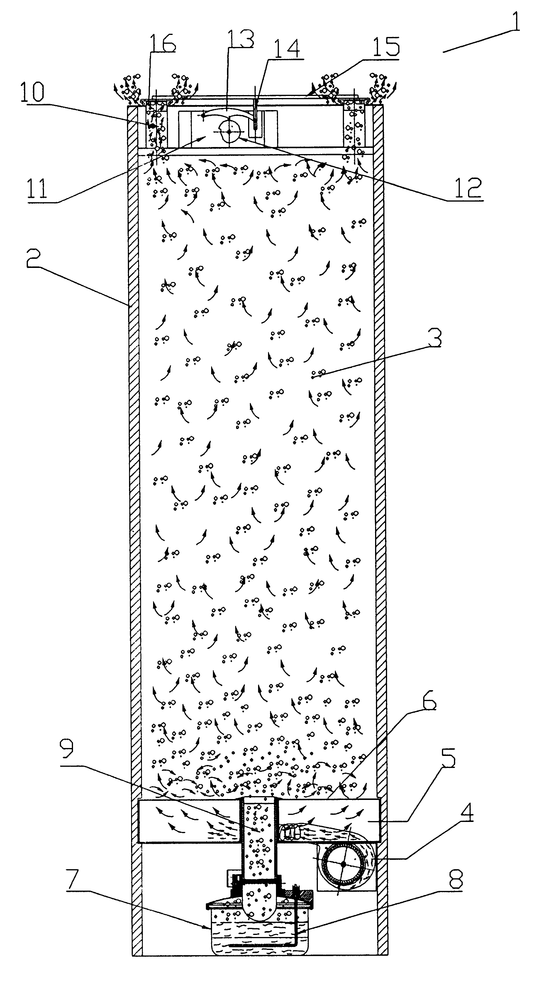
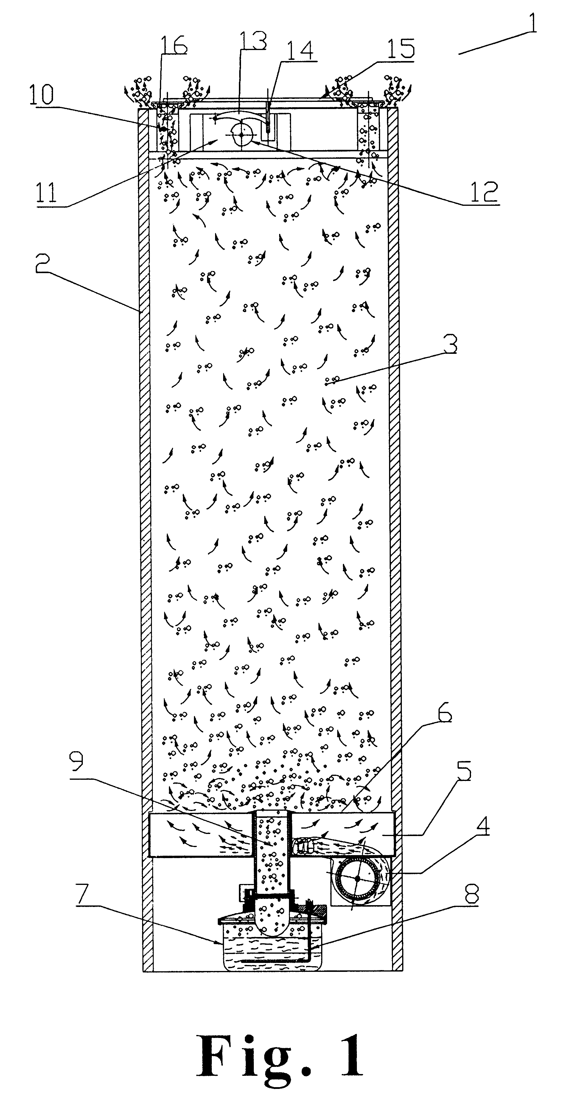
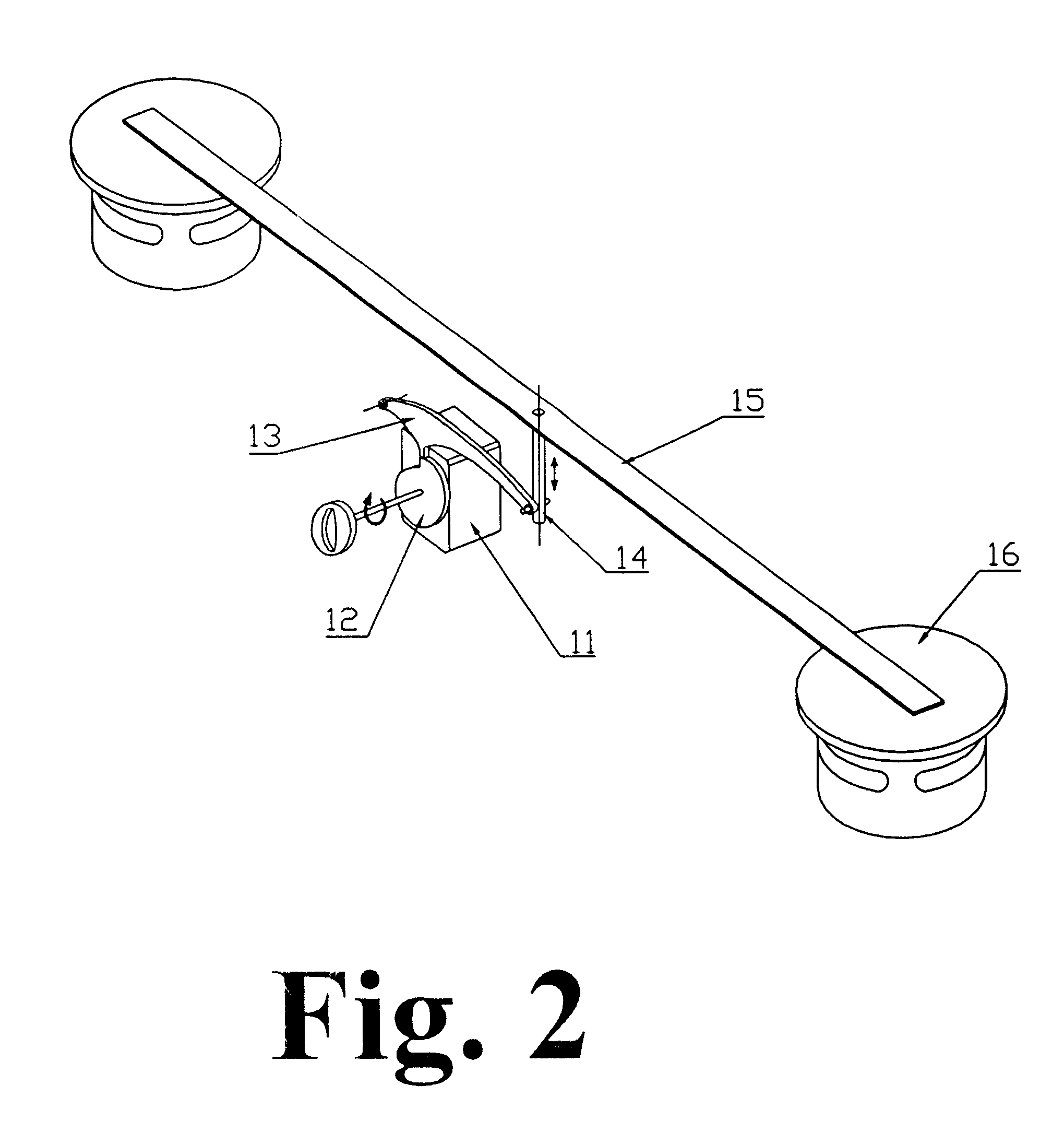
An example of an embodiment of the cabinet that is the object of the present invention is that shown in FIG. 1. Cabinet 1 may have one or more airing ducts 10 and the programmer 11 may be sited at different places in the cabinet 1. This programmer may be either electronic or electromechanical.

It may be observed in the example in FIG. 1 that the cabinet has two airing ducts 10 and the programmer 11 is an electromechanical programmer which is situated at the top of the cabinet 1. As shown in the close view in FIG. 2, in this embodiment the cam follower 13, which rests on the cam 12 of the programmer 11, is linked to a vertical shaft 14, which is in turn linked to a horizontal rod 15, attached to the seals 16. In this way, the seals 16 open or close in accordance with the position of the programmer 11. Naturally, if the programmer 11 were electronic, the transmission means would be different.

In reference again to FIG. 1, the steam supply means include a tank 7 with a resistance 8 that ...


PUM


Abstract

A cabinet for clothes drying and dewrinkling which comprises a main enclosure that defines an inner area for housing clothes, a fan for supplying air to the inner area, a steam generator for supplying steam to the inner area, a controller for regulating the air supply and steam supply, and at least one airing duct. The airing duct can be opened and closed by the controller.

Description

The present invention relates to clothes drying and dewrinkling systems and more specifically to clothes drying and dewrinkling cabinets intended mainly for domestic use.PRIOR ARTIt is a proven fact that one of the most disagreeable household chores is the process that starts off when clean clothes (garments, sheets, etc.) are taken out of the washing machine and finishes when they are stowed away in the respective wardrobe duly ironed (hanging the washing taken out of the washing machine, bringing it in when dry, organizing the ironing thereof, etc.).There have been many attempts to expedite and simplify this process, but no household domestic appliance has been developed to date offering a complete and final solution.Clothes drying cabinets are well known, but they only offer a partial solution to the task that starts after the washing has been done, its main contribution being the speeding-up of the drying process. JP09313793, for instance, claims a booth for clothes drying by me...

Claims


Application Information

Patent Timeline
Patent Type & Authority Patents(United States)
IPC IPC(8): D06F73/00D06F73/02
CPCD06F73/02
Inventor ARRIETA, LUIS JAVIERALBAIZAR, ALBERTO
Owner FAGOR
Why Eureka
Try Eureka