Flexible air ducting

a flexible air and ducting technology, applied in mechanical equipment, lighting and heating equipment, heating types, etc., can solve the problems of high construction cost, relatively easy puncture or torn plastic, and occupants' health hazards, and achieve the effect of greater insulation

Inactive Publication Date: 2002-07-30
ATTRA SHARON L
View PDF13 Cites 17 Cited by
  • Summary
  • Abstract
  • Description
  • Claims
  • Application Information

AI Technical Summary

Benefits of technology

The present invention provides composite flexible air ducting which, as in the prior art, is provided with an elongated inner lining of plastic reinforced by a spirally wound coil member to provide an elongated continuous air passage. A layer of insulation surrounds the inner lining to provide thermal insulation of the air passage from ambient air and an outer sheath surrounds the layer of insulation to provide protection thereto. However, the layer of insulation provided in the flexible air ducting of the present invention is cotton batting or other natural fibrous materials which provide greater insulation and are much less hazardous than fiberglass batting of the prior art.
Thus, the present invention provides flexible air ducting with flexible and versatile characteristics of the prior art but with additional and improved characteristics. The natural fiber insulation eliminates the heath risk associated with fiberglass insulation of the prior art. Technicians manufacturing, installing or servicing the ducting are not required to wear protective clothing or respirator masks. No special clothing or cleaning of clothing and workers is required. Furthermore, the air ducting of the present invention provides substantially greater insulating qualities resulting in more efficient air handling systems, lower energy use and lower energy cost. It's manufacture also requires less energy. Many other objects and advantages of the invention will be understood from reading the specification which follows in conjunction with the accompanying drawings.

Problems solved by technology

Because of obstacles and space restrictions encountered, such construction could be very expensive.
Although there is an inner liner of plastic and spiraled wire in air ducting of the prior art, the plastic may be punctured or torn relatively easily by technicians installing or servicing an air conditioning system.
This, of course, may be hazardous to the occupants thereof.
If a home or building is subsequently altered or demolished, disposal of fiberglass ducting may create contamination and ecological problems.

Method used


Image

  • Flexible air ducting
  • Flexible air ducting

Examples


Embodiment Construction

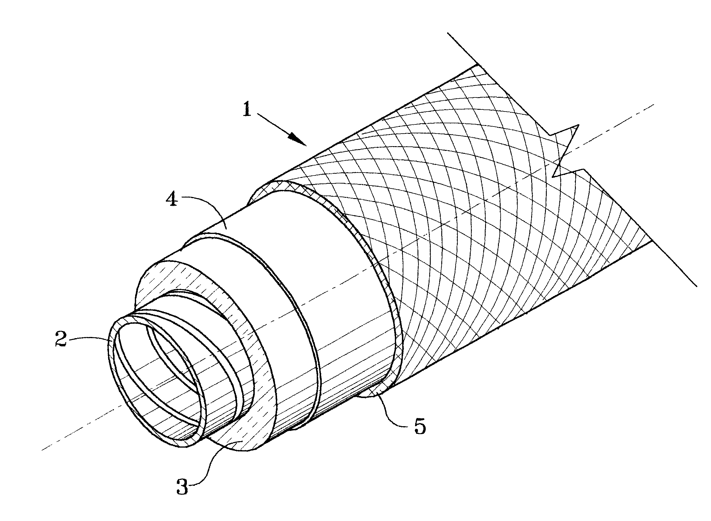
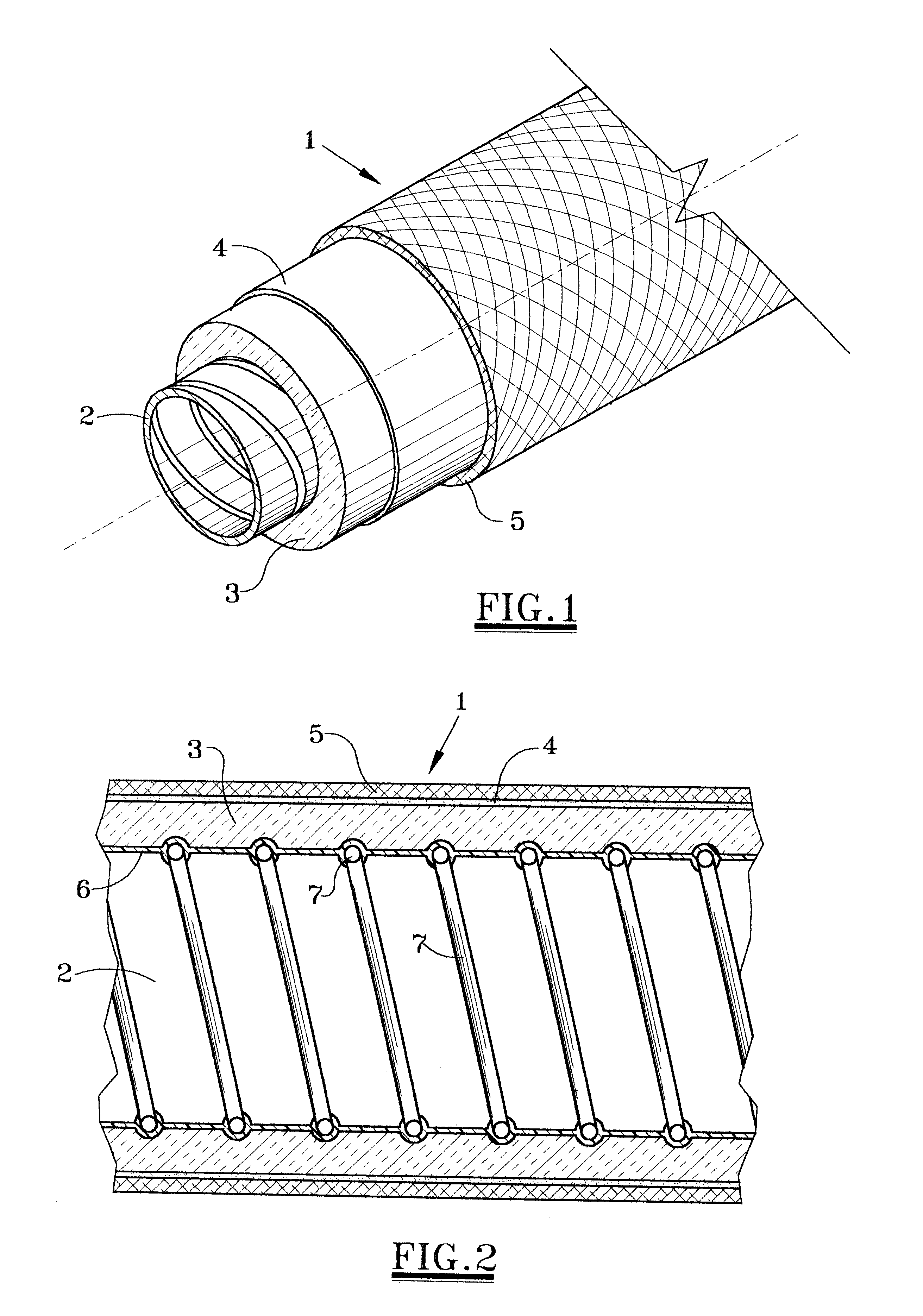
Referring to both FIGS. 1 and 2, there is shown a section of flexible air ducting 1 according to a preferred embodiment of the invention. The ducting 1 comprises an elongated inner liner 2 reinforced by a spirally wound coil member 7 to provide an elongated continuous air passage. Actually, the coil member 7 lies between two thin sheets of plastic which may be heated and bonded together as a composite. The liner 2 is thus formed of relatively thin polyethylene 6 or other plastic material to provide protection from outer layers of the air ducting 1. The spirally wound coil member 7 would typically be a metal material and is primarily for preventing collapse of the ducting 1 which would block flow of air therethrough. The coil member 7 allows the air ducting 1 to be bent or directed around obstacles and through limited spaces without collapsing and without requiring predetermined dimensional specifications therefor.

Surrounding the inner liner 2 is a layer of natural fibrous material 3...


PUM


Abstract

Composite flexible air ducting comprising an elongated inner lining of plastic reinforced by a spirally wound coil member providing an elongated continuous air passage; a layer of natural fiber insulation surrounding the inner lining and an outer sheath surrounding the layer of natural fiber insulation. The outer sheath and the layer of fiber insulation are bonded to each other by a layer of adhesive having substantial thermal insulating properties.

Description

1. Field of the InventionThe present invention pertains to flexible air ducting. More specifically, the present invention pertains to flexible ducting utilized for conveying air in heating and air conditioning systems.2. Description of the Prior ArtAir conditioning systems for heating and / or cooling air are typically provided with cooling and heating equipment by which ambient air is heated or cooled depending upon the particular need. The heated or cooled air is then forced by an air handler of some type through air ducting for distribution to areas where needed, e.g. the rooms of a residence or building.In the past, such ducting typically comprised passageways formed by sheet metal wrapped or covered with insulation. The use of sheet metal required construction to specific dimensions for moving the air from one point to another. Because of obstacles and space restrictions encountered, such construction could be very expensive.In more recent times, flexible ducting has been develop...

Claims


Application Information

Patent Timeline
Patent Type & Authority Patents(United States)
IPC IPC(8): F16L11/08
CPCF16L11/081F24F13/0218F24F13/0263
Inventor ATTRA, SHARON L.
Owner ATTRA SHARON L
Why Eureka
Try Eureka