Valve timing control device

a timing control and valve technology, applied in the direction of threaded fasteners, machines/engines, screws, etc., can solve the problems of bolt 11 being caught in the moving parts of the internal combustion, affecting the timing control of the opening and closing of the valve, and loosing or detaching bolt 11 , to achieve the effect of preventing internal combustion from failure, ensuring device reliability, and preventing oil leakag

Inactive Publication Date: 2002-08-13
MITSUBISHI ELECTRIC CORP
View PDF4 Cites 1 Cited by
  • Summary
  • Abstract
  • Description
  • Claims
  • Application Information

AI Technical Summary

Benefits of technology

, a valve timing control device comprises a camshaft opening and closing at least one intake and exhaust valves in an internal combustion; an input rotational member arranged on the camshaft to input the rotational driving force of the internal combustion; a case whose end is assembled in the input rotational member in an axial direction of the case; a rotor accommodated in the case to rotate relative to the case and coupled to the camshaft; a cover member disposed at the other end of the case in the axial direction; a threaded member used for being integrated with the cover member, the case and the input rotational member; and a detachment prevention means arranged at the threaded member to prevent the loosening and detachment of the threaded member. In this way, the threaded member is not detached or loosened due to the vibration caused by driving the internal combustion. It is therefore possible to prevent oil leaks resulting from the loosening of the threaded member and prevent the internal combustion from failure resulting from the detachment of the threaded member. As a result, it is possible to ensure reliability of the device, and increases durability thereof.

Problems solved by technology

As a result, there is a problem that the bolt 11 becomes loose or detaches due to the vibration caused by driving the internal combustion at high speed.
As a result, oil leaks from the retardation side hydraulic pressure chamber 14 or the advance side hydraulic pressure chamber 15 and results in adverse effects on the control of the opening and closing timing of the valves.
If the bolt 11 detaches and falls into the engine room, there is a problem that the bolt 11 gets caught in the moving parts of the internal combustion.
As a result, the leakage of oil from the retardation side hydraulic pressure chamber 14 or the advance side hydraulic pressure chamber 15 is increased and results in reduced performance in controlling the valve timing control device.

Method used


Image

  • Valve timing control device
  • Valve timing control device
  • Valve timing control device

Examples


embodiment 1

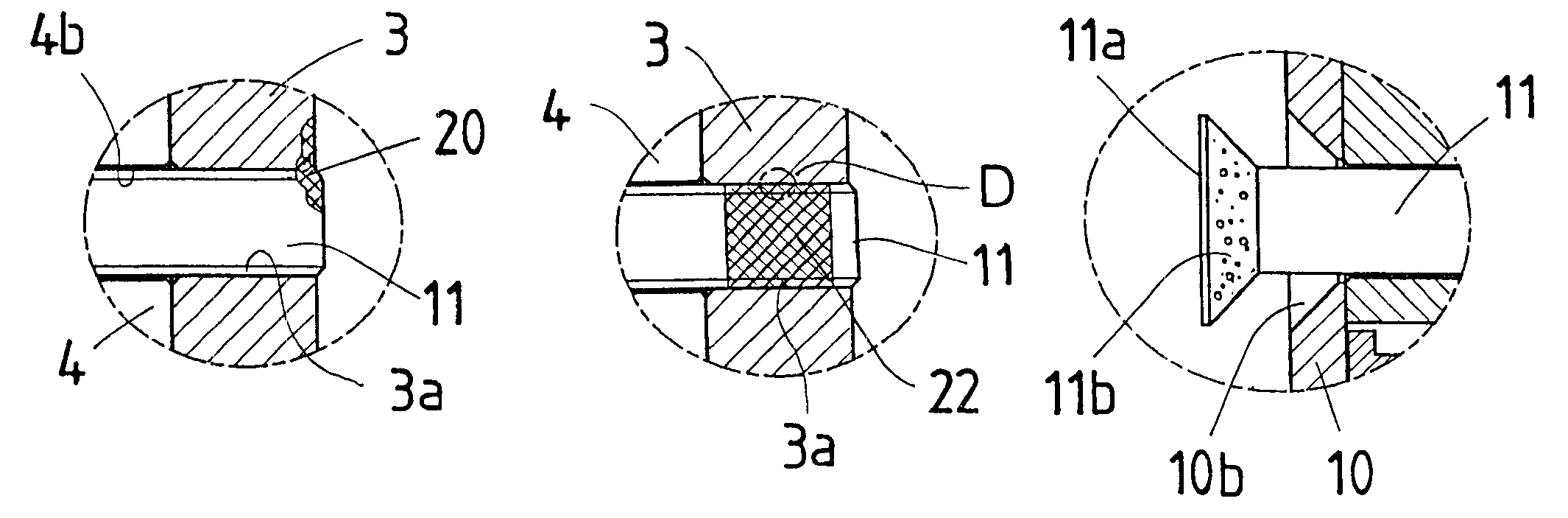
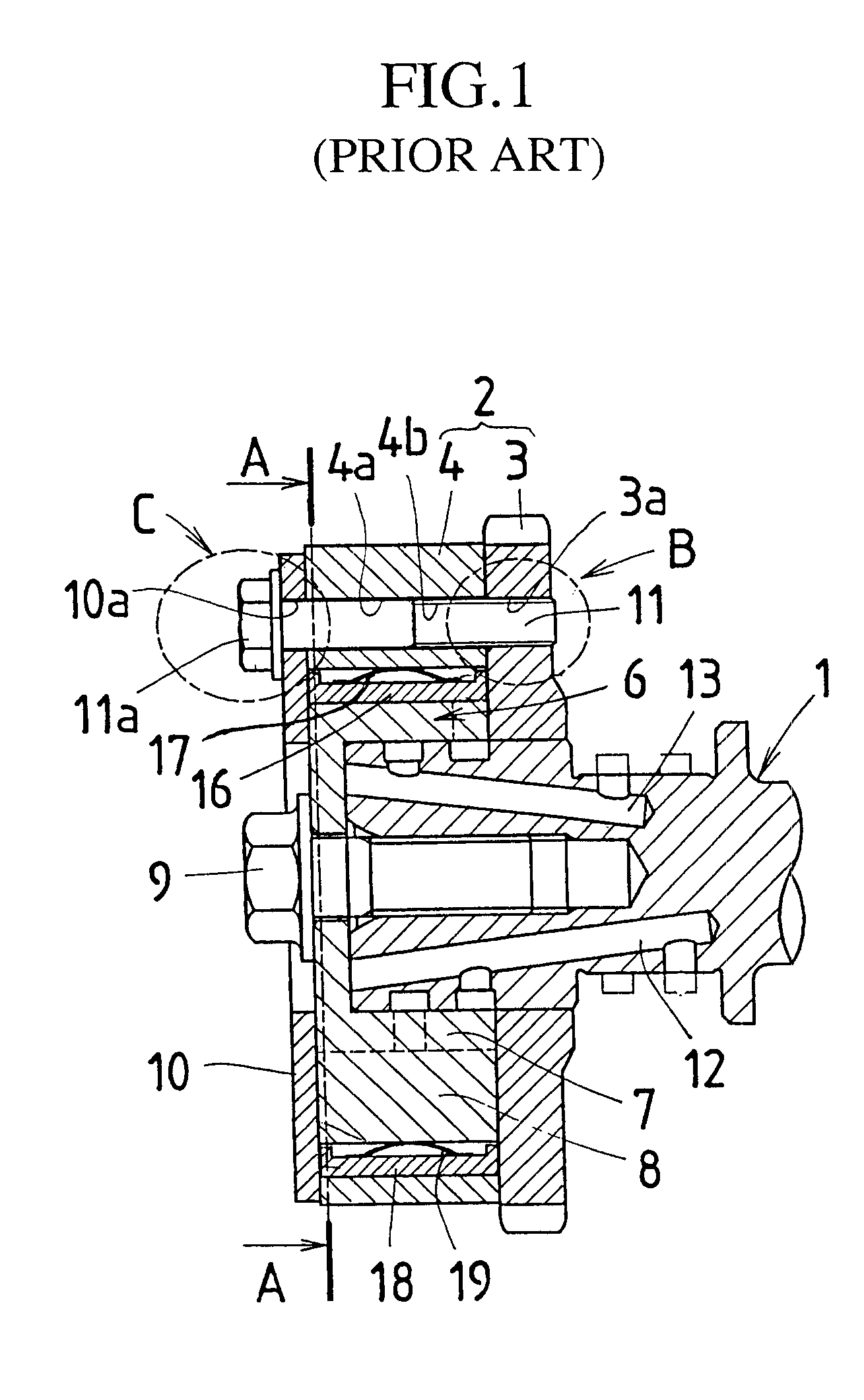
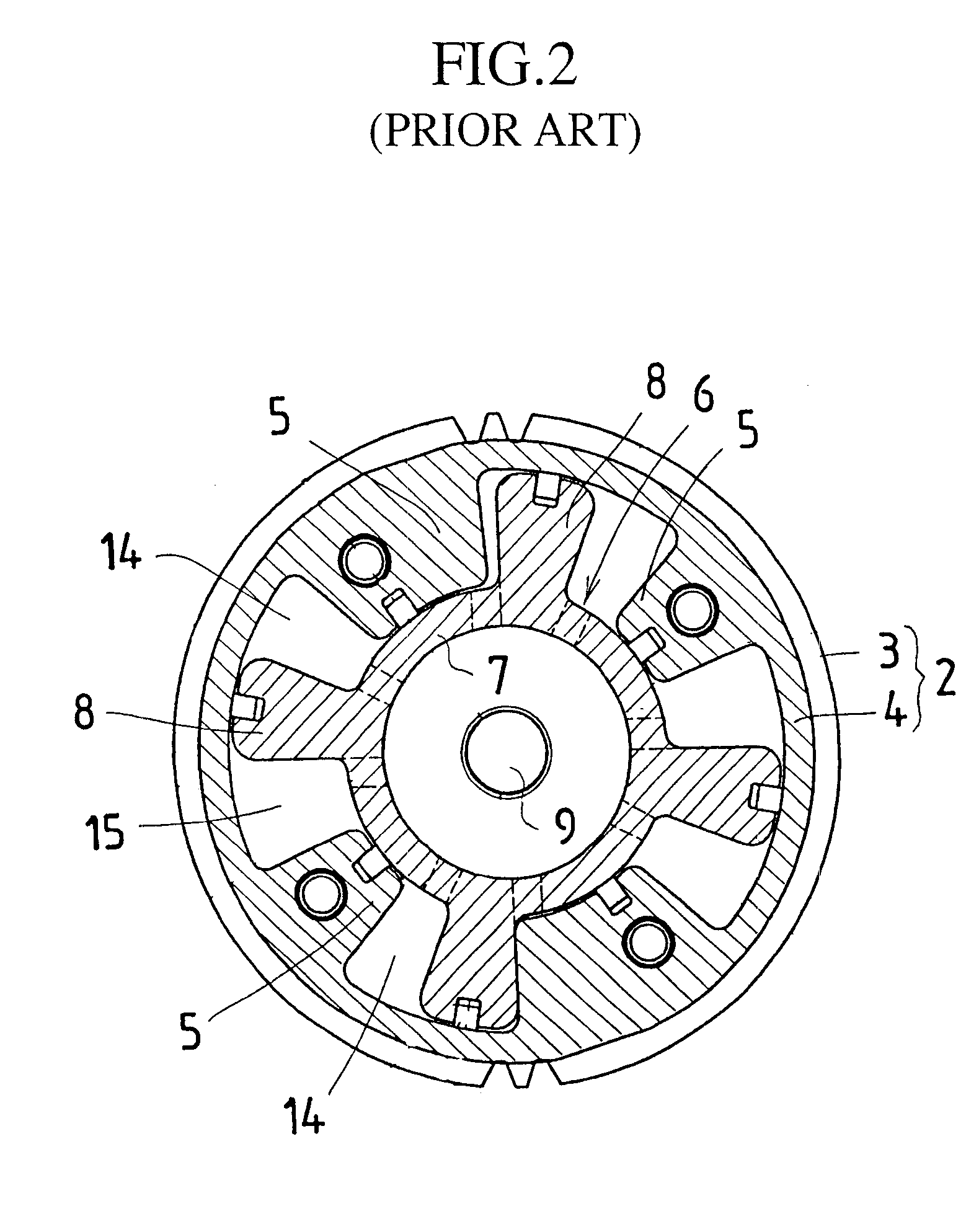
FIG. 3A is an enlarged fragmentary cross sectional view showing a part corresponding to part B of FIG. 1. FIG. 3B is a longitudinal cross sectional view of main points of a valve timing control device as embodiment 1 according to the present invention, and shows a state after welding a threaded member to an input rotational member shown in FIG. 3A. Since the common numerals of the embodiment 1 denote common elements in the conventional device of FIG. 1 and FIG. 2, the description of such parts is omitted.

In FIG. 3B, numeral 20 denotes a welding section welding the input rotational member 3 to the bolt (threaded member) 11. With the embodiment 1, the input rotational member 3, the case 4 and the cover member 10, which are the same components as the conventional device of FIG. 1 and FIG. 2, are integrated by threadable attachment of the bolt 11 in a manner similar to the prior art. The front end of the bolt 11 is then welded to the input rotational member 3. The welding section 20 mea...

embodiment 2

FIG. 4A is an enlarged fragmentary cross sectional view showing a part corresponding to part B of FIG. 1. FIG. 4B is a cross sectional view of main points of a valve timing control device as embodiment 2 according to the present invention, and shows a state after swaging a threaded member to an input rotational member shown in FIG. 4A. Since the common numerals of the embodiment 2 denote common elements in the conventional device of FIG. 1 and FIG. 2 and common elements in the embodiment 1, the description of such parts is omitted.

In FIG. 4A and FIG. 4B, numeral 21 denotes a recess arranged at the front end of the bolt 11. Numeral 21a denotes a swaging section formed by outwardly bending a peripheral wall of the recess 21 to swage the peripheral wall toward an outer side face of the input rotational member 3. With the embodiment 2, after the front end of the bolt 11 is screwed in the bolt threaded hole 3a of the input rotational member 3 on assembling the housing 2 in a manner simil...

embodiment 3

FIG. 5A is an enlarged fragmentary cross sectional view showing a bolt before adhering to an input rotational member. FIG. 5B is a cross sectional view of main points of a valve timing control device as embodiment 3 according to the present invention, and shows a state after adhering the bolt to the input rotational member shown in FIG. 5A. FIG. 5C is an enlarged fragmentary cross sectional view showing part D of FIG. 5B. Since the common numerals of the embodiment 3 denote common elements in the conventional device of FIG. 1 and FIG. 2 and common elements in the embodiments 1 and 2, the description of such parts is omitted.

In FIG. 5A, FIG. 5B and FIG. 5C, numeral 22 denotes an adhesive applied to the front end of the bolt 11. With the embodiment 3, the adhesive 22 is previously applied to a threaded section of the front end of the bolt 11 to hold it to the bolt threaded hole 3a of the input rotational member 3 on assembling the housing 2. The front end of the bolt 11 is then screwe...


PUM


Abstract

A valve timing control device has an input rotational member 3, a case 4, and a cover member 10, which constitute a housing 2. A threaded member 11 such as a bolt is used for being integrated with the cover member 10, the case 4 and the input rotational member 3. A welding section 20 is formed at the bolt 11 to prevent the loosening and detachment of the bolt 11.

Description

1. Field of the InventionThe present invention relates to a valve timing control device for modifying the opening and closing timing of at least one of an intake or an exhaust valve in an internal combustion engine (hereafter, referred as an engine) in response to any operating condition.2. Description of the Prior ArtFIG. 1 is a longitudinal cross sectional view of a conventional valve timing control device. FIG. 2 is a longitudinal cross sectional view taken along lines A--A of FIG. 1.In FIG. 1, reference numeral 1 denotes a camshaft opening and closing the intake and exhaust valves in the internal combustion. Numeral 2 denotes a housing, which is rotatably fitted in and held on the camshaft 1. The housing 2 includes an input rotational member 3 constituted by a timing-sprocket or a timing-pulley inputting a rotational driving force from a crankshaft (not shown) of the engine to this device; and a cylindrical-shaped case 4 having a through hole, fixedly mounted on a side of the in...

Claims


Application Information

Patent Timeline
Patent Type & Authority Patents(United States)
IPC IPC(8): F01L1/344F01L1/34F16B39/01F16B39/02F16B39/22F16B39/24F16B39/282
CPCF01L1/3442F01L2001/34479
Inventor YAMAUCHI, MAKOTOKINUGAWA, HIROYUKI
Owner MITSUBISHI ELECTRIC CORP
Why Eureka
Try Eureka