Device for storing compressed gas

Inactive Publication Date: 2002-08-13
MANNESMANN AG
View PDF15 Cites 103 Cited by
  • Summary
  • Abstract
  • Description
  • Claims
  • Application Information

AI Technical Summary

Problems solved by technology

However, this store has significant drawbacks, in particular on account of its high overall weight.
Particularly when using the storage device as a fuel tank for vehicles, it is not always possible--on account of the installation space available in the vehicle--to use a cylindrical vessel.
This is because the escape of particles into downstream e

Method used


Image

  • Device for storing compressed gas
  • Device for storing compressed gas
  • Device for storing compressed gas

Examples


Example

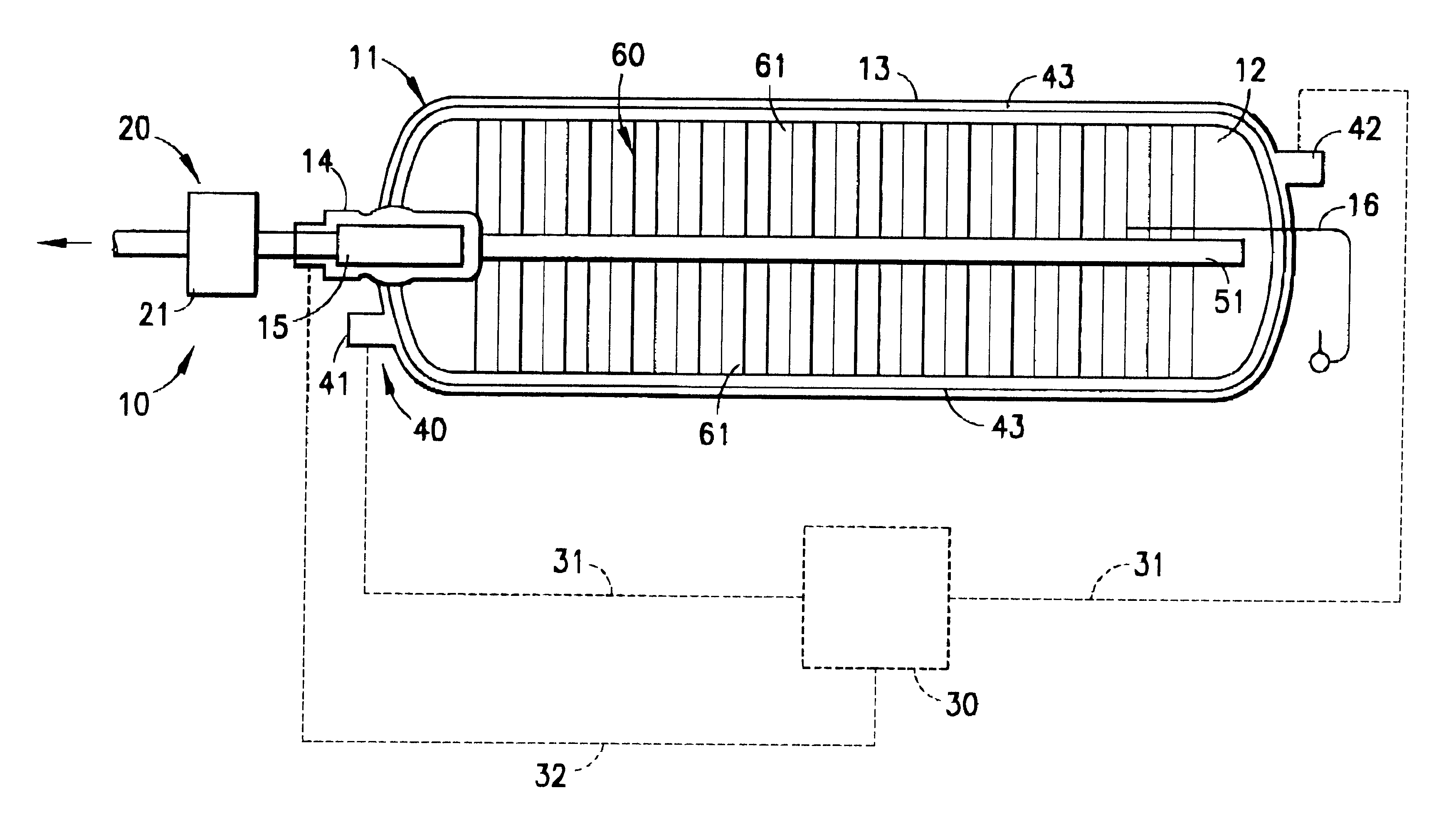
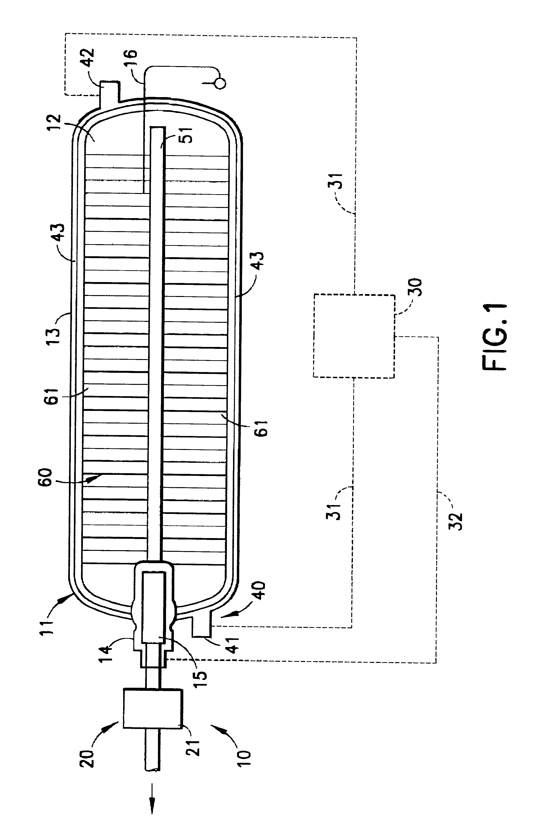
FIG. 1 shows a device 10 for storing compressed gas which has a closed storage vessel 11. The storage vessel 11 has a vessel wall 13 which delimits an interior 12 for accommodating a solid filling 60. The storage vessel 11 also has a feed and discharge line 14, via which it can be charged with compressed gas and compressed gas can be discharged. To prevent an undesirable discharge of particles of the solid filling 60 from the storage vessel 11, a filter element 15, which is designed as a microfilter, is provided in the feed and discharge line 14. The temperature in the interior 12 of the storage vessel 11 is determined by means of a temperature sensor 16.

The device 10 for storing compressed gas also has a heating / cooling device 40, which is formed from an inlet connection piece 41, an outlet connection piece 42 and a cooling passage 43. The inlet connection piece 41 and the outlet connection piece 42 are formed in the vessel wall 13 of the storage vessel 11 and are connected to a so...


PUM

PropertyMeasurementUnit
Pressureaaaaaaaaaa
Temperatureaaaaaaaaaa
Densityaaaaaaaaaa

Abstract

A closed storage reservoir has at least one feed and discharge line for compressed gas and, in its interior, a gas flow control system which connects the feed and discharge line to a solid filling for storing the compressed gas in the interior. To ensure the highest possible specific storage capacity of the device and to enable the device to be used as a tank system for a fuel cell, the solid filling comprises carbon nanostructures which are joined to form larger, cohesive conglomerates. A device for measuring the filling level of the compressed gas in the storage vessel may be a device for measuring the nuclear magnetic resonance or a device for measuring the mass flow rates of the compressed gas. A temperature sensor and a heating/cooling device having an inlet connection piece and an outlet connection piece for a heating/cooling medium and a cooling passage connected to the connection pieces are provided in order to set a defined temperature in the storage vessel.

Description

1. Field of the InventionThe present invention relates to a device for storing compressed gas, in particular hydrogen, having at least one closed storage vessel which has at least one feed and discharge line for the compressed gas and, in its interior, a gas flow control system, the gas flow control system being connected to the feed and discharge line for the compressed gas, and in which a solid filling for storing the compressed gas is provided in the interior.The storage of hydrogen in normal pressure vessels presents particularly significant difficulties if the maximum possible filling density based on the vessel volume is to be achieved.2. Description of the Related ArtU.S. Pat. No. 4,964,524 discloses a device for storing compressed gas as described in the introduction, in which hydride-forming metal alloys form a fine particulate filling, having a storage capacity which is high with respect to the volume. However, this store has significant drawbacks, in particular on account...

Claims


Application Information

Patent Timeline
IPC IPC(8): C01B3/00F17C11/00
CPCB82Y30/00C01B3/0021F17C11/005Y02E60/321Y02E60/325Y02E60/327Y10S977/742Y10S977/948Y10S977/842Y02E60/32
Inventor KLOS, HOLGERSCHUTZ, WALTER
Owner MANNESMANN AG
Why Eureka
Try Eureka