Regeneration system for an exhaust gas cleaning device

a technology of exhaust gas cleaning and regeneration system, which is applied in the direction of auxillary pretreatment, separation process, filtration separation, etc., can solve the problem of brittle rupture, the amount of particulate to be treated in one regeneration of the cordierite filter has a limit, and the formation of particulate cannot be completely controlled

Inactive Publication Date: 2002-09-10
IBIDEN CO LTD
View PDF15 Cites 87 Cited by
  • Summary
  • Abstract
  • Description
  • Claims
  • Application Information

AI Technical Summary

Problems solved by technology

Particularly, when the filter is made from a ceramic material, brittle rupture is caused by thermal stress to create cracks.
However, the formation of the particulate can not completely be controlled even by using such a fuel additive and hence the particulate is formed in the exhaust gas.
However, there is a problem that the amount of the particulate to be treated in one regeneration of the cordierite filter has a limit because the maximum service temperature in the filter is low.
In this case, a large pressure loss is caused in the filter due to the deposition of the particulate, so that the combustion efficiency of the internal combustion engine lowers to degrade the fuel consumption.
However, when such a greater amount of the particulate caught on the filter is burnt out by the heating means at once, a large change of the pressure loss is caused in the burning of the particulate in accordance with the heat conduction efficiency of the heating means, which gives incompatible feeling to a driver.
In the conventional cordierite filter, however, there is a limit in the formation of the fine cell structure from a view point of the strength inherent to the cordierite.
For example, it is possible to manufacture the cordierite honeycomb filter having the cell number Nc of more than 100 cpi, but when such a filter is used as a checkered honeycomb filter capable of efficiently burning the particulate, the cracking is caused in view of the crack limit of cordierite itself, so that the cell number Nc (cpi) can not be made more than 100 when the checkered honeycomb filter for cleaning the exhaust gas is made of cordierite.
In addition, if it is intended to burn the deposited particulates through only the temperature of the exhaust gas, there is caused an inconvenience that the honeycomb filter for cleaning the exhaust gas can not completely be regenerated because the exhaust gas may not rise to a temperature required for burning the particulate when the vehicle is frequently run on urban area at a low speed.
When the total volume of the filter is less than 1 / 4 times the engine swept volume, the sufficient filtering area can not be ensured and the pressure loss becomes larger to bring about the remarkable degradation of the fuel consumption, while when it exceeds 2.0 times, it is difficult to arrange the exhaust gas cleaning device inclusive of the filter in the exhaust emission path but also the thermal capacity becomes larger to delay reaction to the temperature of the exhaust gas to thereby lose a chance of obtaining a regeneratable temperature of the filter for burning the particulate.

Method used


Image

  • Regeneration system for an exhaust gas cleaning device
  • Regeneration system for an exhaust gas cleaning device
  • Regeneration system for an exhaust gas cleaning device

Examples


first embodiment

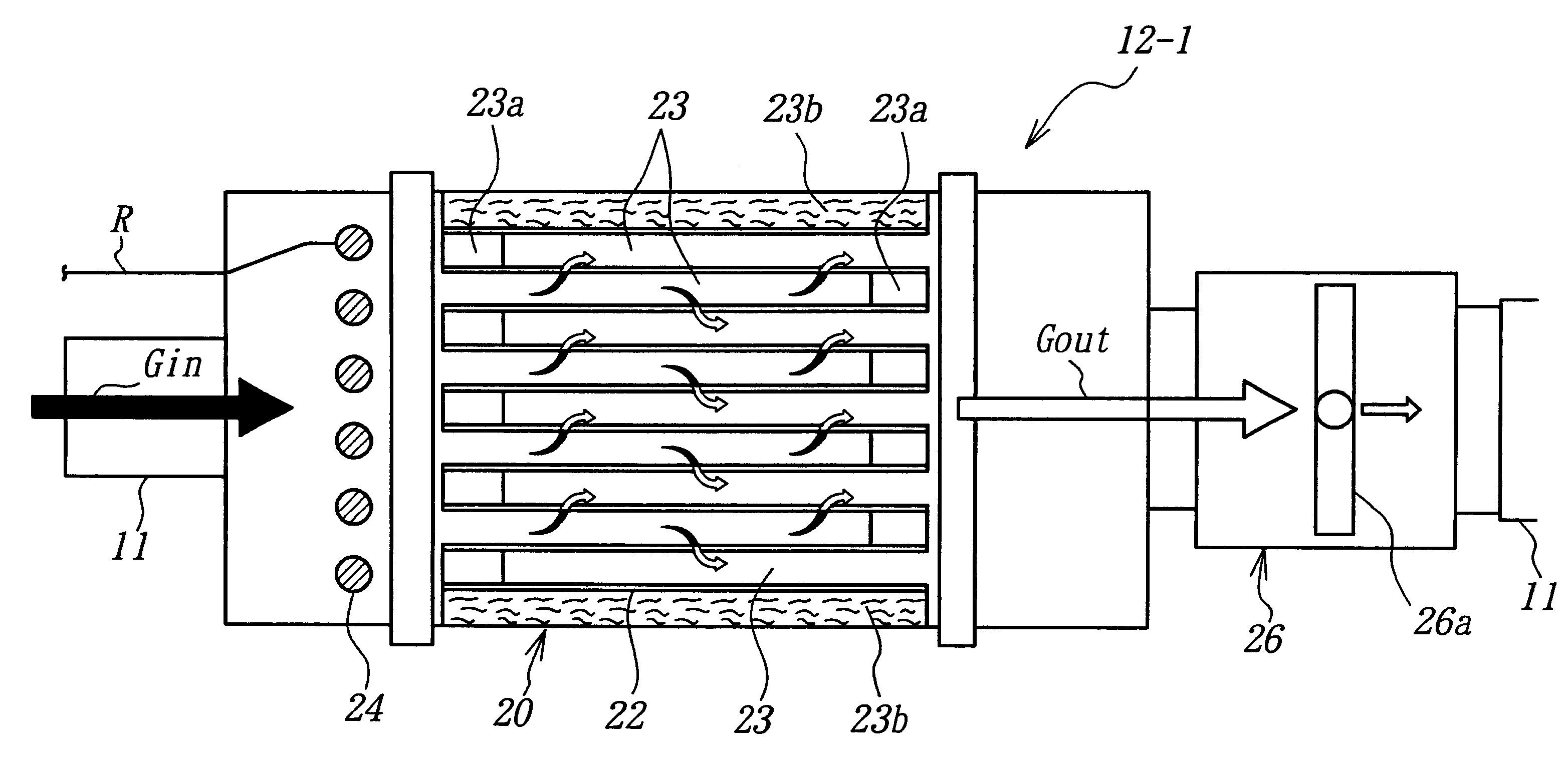
In FIG. 4 is shown the regeneration system for the exhaust gas cleaning device for use in a diesel engine according to the invention. This system is a system for the regeneration of an exhaust gas cleaning device 20 cleaning the exhaust gas discharged from a diesel engine 10 using a gas oil containing a fuel additive, and comprises three regeneration units 12-1, 12-2, 12-3 disposed on a way of an exhaust emission path 11 from the engine 10 in a branched form. Each of these units comprises an exhaust gas cleaning device 20 provided with an exhaust gas cleaning filter 22 made of a porous silicon carbide (SiC) sintered body and carried with a catalyst for exhaust gas purification, a heating means 24 disposed ahead an end face of the SiC filter 22 at an upstream side thereof for heating the SiC filter 22, and a flow control valve 26 disposed at a downstream side of the SiC filter 22. Further, the regeneration system comprises a control unit 40 for controlling power supplied to the heati...

second embodiment

the regeneration system for the exhaust gas cleaning device for use in a diesel engine according to the invention has the same structure as in the first embodiment except that a glow plug 34 is used instead of the heater as the heating means 24 as shown in FIG. 7. As the glow plug 34, there are two plugs as shown in FIGS. 7a and 7b. The plug shown in FIG. 7a is a ceramic glow plug 34a using an electrically conductive ceramic 35 attached to a top of the plug as a heating portion, wherein heat is generated by flowing current through the electrically conductive ceramic 35. The plug shown in FIG. 7b is a metal glow plug 34b using a heating coil 36 attached to the top of the plug as a heating part, wherein heat is generated by flowing current through the heating coil 36.

In FIG. 8 is shown a comparison in properties between the ceramic glow plug 34a and the metal glow plug 34b. In this case, the time reaching to 800.degree. C. by heating is a surface temperature rising rate of the heating...


PUM

PropertyMeasurementUnit
temperatureaaaaaaaaaa
thicknessaaaaaaaaaa
temperatureaaaaaaaaaa

Abstract

A regeneration system for an exhaust gas cleaning device disposed in an exhaust emission path of an internal combustion engine has an exhaust gas cleaning honeycomb filter and a heating element for the filter, wherein the filter is a checkered SiC honeycomb filter having a given cell structure, and the heating element is a heater or a glow plug when using a fuel containing fuel additive.

Description

1. Field of the InventionThis invention relates to a regeneration system for an exhaust gas cleaning device, and more particularly to a regeneration system comprising an exhaust gas cleaning device disposed in an exhaust emission path of an internal combustion engine and provided with an exhaust gas cleaning honeycomb filter for catching particulates included in the exhaust gas and a heating means for the exhaust gas cleaning honeycomb filter when a fuel containing a fuel additive for mitigating particulates included in the exhaust gas is used as a fuel for the internal combustion engine.2. Description of Related ArtIn the internal combustion engine such as diesel engine or the like, particulates (e.g. soot or unburned portion of fuel) are included in the exhaust gas. Particularly, the discharge amount of particulates becomes large in a diesel engine using a gas oil as a fuel or a direct-injection type gasoline engine recently coming into wide use. Therefore, it is well-known to rem...

Claims


Application Information

Patent Timeline
Patent Type & Authority Patents(United States)
IPC IPC(8): B01D53/96B01D53/94F01N3/022F01N3/023F01N3/035F01N3/027F01N3/031F01N3/032B01D46/00F01N3/02
CPCB01D53/9454B01D53/96F01N3/027F01N3/032F01N3/035F01N2240/16F01N2330/14F01N2510/06Y10S55/30Y10S55/10Y02T10/22Y02T10/12
Inventor OHNO, KAZUSHIGEKOMORI, TERUONINOMIYA, TAKESHITAOKA, NORIYUKIHONG, SUNGTAE
Owner IBIDEN CO LTD
Why Eureka
Try Eureka