

Polymeric articles having embedded phases
a technology of polymer articles and phases, applied in the field of polymer articles having embedded phases, can solve the problems of narrowing the suitable use range, oriented polypropylene webs do not traditionally make satisfactory products requiring cross-web strength, and the cross-web tear strength is not desirable, so as to achieve the effect of reducing the contact time in the di
Inactive Publication Date: 2002-09-10
3M INNOVATIVE PROPERTIES CO
View PDF39 Cites 41 Cited by
- Summary
- Abstract
- Description
- Claims
- Application Information
AI Technical Summary
Benefits of technology
The present invention is also directed to an extrusion die for forming a polymeric co-extruded web. In specific embodiments, the die includes a body containing two chambers. An adjustable vane is positioned between the chambers. The adjustable vane is at least partially hollow, having a cavity within its interior. The vane has at least one opening (inlet) in the cavity positioned to receive a material being extruded, and at least two openings (outlets) in the cavity positioned in a tip to extrude material into the body of the die. The cavity inlets and outlets are sized so that the width of the embedded phases extruded from the vane outlets into the die body are uniform. This uniformity of the embedded phases is an advantage of this invention.
The invention is further directed to a process of making a polymeric co-extruded web. The process includes providing an extrudable material and an extrusion die. In a specific embodiment, the die contains two chambers and an adjustable vane between the chambers. The vane contains a cavity having at least one input orifice positioned to receive extrudable material and at least two exit orifices. The cavity is designed so that the pressure drop of molten polymer within the cavity is significantly less than the pressure drop through the exit orifices to yield embedded phases of improved width uniformity over those extruded by known techniques. A first material is extruded through the chambers of the die, and a second material is extruded through the exit orifice in the vane to produce a co-extruded web containing the first and second extrudable materials. The second material is embedded between the two layers of the first material. Alternatively, different polymeric materials may pass through each die chamber to form two layers of different materials that are positioned around the embedded phase material.
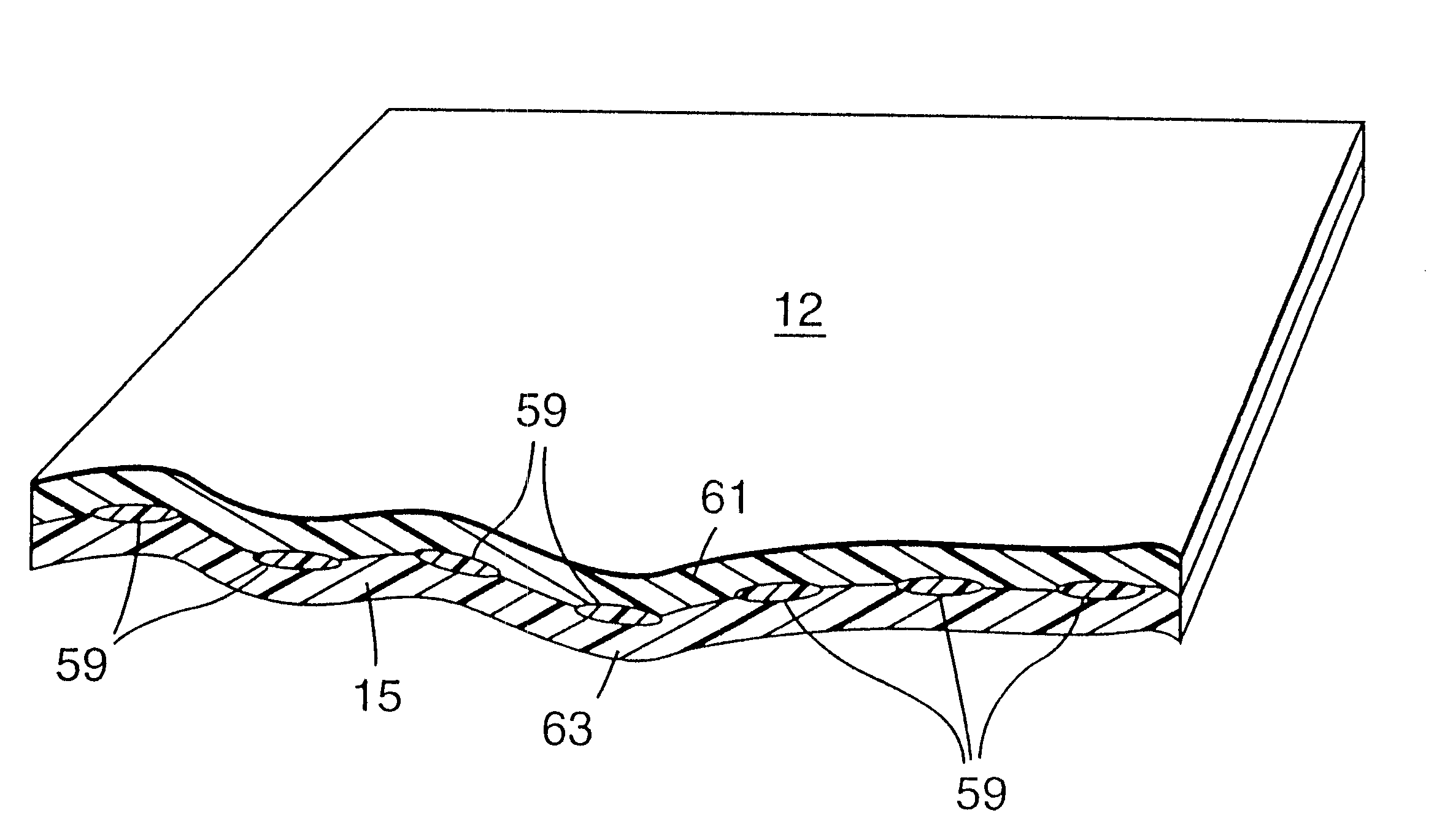
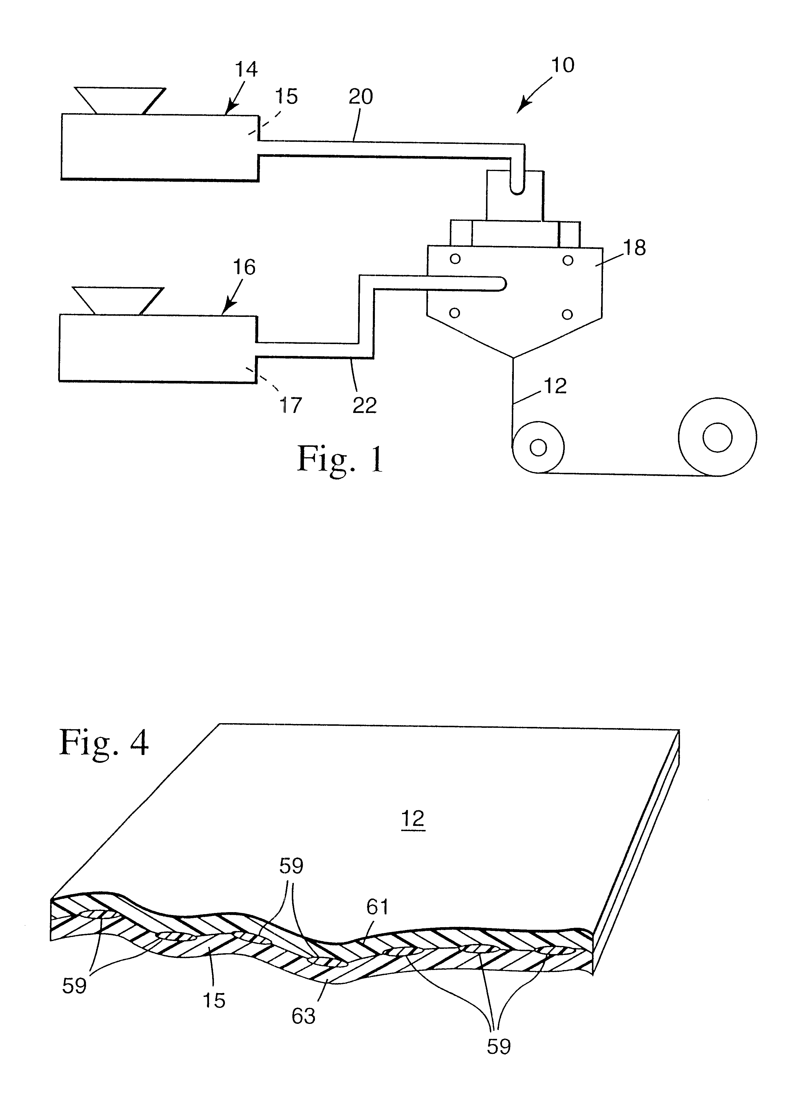
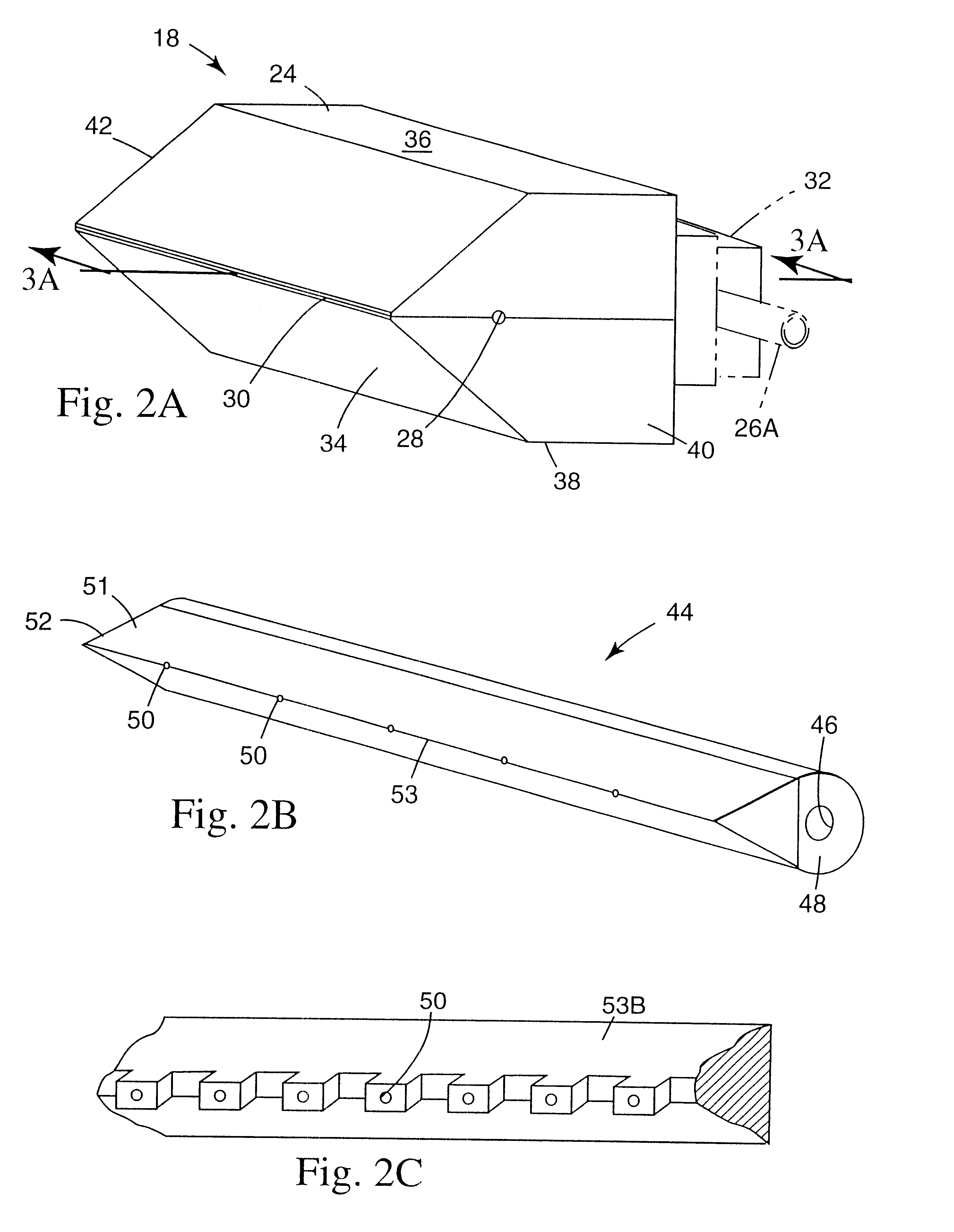
The present invention is advantageous in that materials 15, 17 are co-extruded in a controlled manner. The materials are brought together in the melt state, thereby allowing for improved adhesion to one another. In addition, even when the materials are not normally compatible, they may still be co-extruded in order to produce a web retaining the properties of each of the materials. In the embodiment shown, the discrete embedded phases 59 have substantially uniform width when the orifices in vane tip 53 are substantially uniform. Although the phases 59 are often uniformly spaced across the web 12, the width, and spacing of the phases can be altered by providing different tips 53 for vane 44. The large volume of cavity 60 where the second material first enters vane 44 compared to the small volume of exit orifices 50 in the front portion 53 of vane 44 is preferred in order to obtain a pressure drop of the second material through the length of the cavity substantially less than its pressure drop through the exit orifices.
In reference now to FIGS. 5A, 5B, 5C and 5D, various configurations of vane tip 53 are shown that produce different coextruded webs. In FIGS. 5A and 5B, the resultant web will have a multiplicity of discrete polymeric phases across its width. Each orifice of tip 53B is extended as shown in FIG. 2C to minimize the contact time in the die between the discontinuous phases and the layers of the continuous matrix. Tip 53C shown in FIG. 5C will yield,.a plurality of discrete embedded phases on each of the two edges of the extruded web, and tip 53D shown in FIG. 5D will yield one discrete embedded phase proximate each edge of the web. A web manufactured using tip 53D can be particularly suitable for cross-web stretching, since the thickened or reinforced portions on the edge of the web will provide a position onto which a stretching apparatus (e.g., tenter clips) can grab when stretching the web in a cross-web direction.
Problems solved by technology
Although these polymeric materials and others are suitable for use in forming a polymeric web, they can have limiting characteristics that substantially narrow their suitable uses.
For example, reinforced polypropylene webs often have very good tensile strength, but have less than desirable cross-web tear strength.
Therefore, due to a propensity to tear too easily in the cross-web direction, oriented polypropylene webs do not traditionally make satisfactory products requiring cross-web strength, such as strapping tape products.
Similarly, natural and synthetic rubber have excellent elasticity, but are difficult to fuse with most polymeric materials.
Therefore, due to the challenge of creating a good bond between materials, rubber webs are difficult to use in products that require them to be joined with other polymeric materials.
Method used
View moreImage
Smart ImageViewing Examples

Examples
example 2
xample 1 except the continuous matrix material extruder was run at 20 rpm with a head pressure of 12.4 MPa (1800 psi) to feed matrix material at a rate of about 11.8 kg / hr (26.0 lbs / hr).
examples 3-5
Examples 3-5 demonstrate changing melt viscosity of the embedded phase material on constructions having inelastic matrices and elastic embedded phases.
example 3
n Example 1 except some process conditions were changed. The matrix material extruder was run at 30 rpm with a head pressure of 15.2 MPa (2200 psi) to feed matrix material. The embedded phase material extruder was run at 80 rpm with a head pressure of 13.8 MPa (2000 psi) to feed embedded phase material. The web take-away system ran at a speed of about 16.8 m / min (40 fpm).
Login to View More PUM
| Property | Measurement | Unit |
|---|---|---|
| width | aaaaa | aaaaa |
| width | aaaaa | aaaaa |
| length | aaaaa | aaaaa |
Abstract
A die apparatus, a method of using the die apparatus to produce co-extruded polymeric articles, and co-extruded polymeric articles produced using the die apparatus and method are disclosed. The die apparatus includes a hollow vane configured to extrude a material into a chamber within the die, thereby producing a co-extruded web. The co-extruded web has a plurality of distinct, discontinuous phases in the cross-web direction, the phases having a uniform width as shown by a coefficient of variation of less than 8 percent for any three consecutive phases. The phases are substantially continuous down-web and are surrounded by a matrix having two or more layers.
Description
The present invention is directed to an extrusion die, a method of using the die to produce co extruded polymeric articles, and co-extruded polymeric articles produced therewith having internal discontinuities, such as stripes.Extruded polymeric webs are used in many applications, including the production of thin films for use as tape backings, medical films, and vapor barriers. Polymeric materials that are suitable for extrusion are often polyolefins such as polyethylene, polypropylene, and polybutylene, polyamides such as nylon; polyesters such as polyethylene terephthalate or polyvinylidene fluoride. Although these polymeric materials and others are suitable for use in forming a polymeric web, they can have limiting characteristics that substantially narrow their suitable uses. For example, reinforced polypropylene webs often have very good tensile strength, but have less than desirable cross-web tear strength. Therefore, due to a propensity to tear too easily in the cross-web di...
Claims
Login to View More Application Information
Patent Timeline
 Patent Type & AuthorityPatents(United States)
IPC IPC(8): A61F13/02A61F13/00B32B27/00B29C47/04B29K23/00B29L9/00B29L31/00B32B27/12B32B27/32
CPCA61F13/02A61F2013/00608A61F2013/00855Y10T428/2457Y10T428/28Y10T428/24752Y10T428/24074A61F13/0206A61F13/0209A61F13/0246
InventorNORQUIST, SCOTT G.KRUEGER, DENNIS L.SIPINEN, ALAN J.MENZIES, ROBERT H.HANSCHEN, THOMAS P.LESEMAN, RONALD P.MITCHELL, SHARON N.NYGARD, JAMES C.THALACKER, VICTOR P.OCKELOEN, JAN
Owner3M INNOVATIVE PROPERTIES CO