Method and apparatus for time synchronization in a communication system

a communication system and time synchronization technology, applied in the field of communication systems, can solve the problems of slow crystal response, many seconds or even minutes, and increase the difficulty of synchronizing time,

Inactive Publication Date: 2002-09-10
HEWLETT PACKARD DEV CO LP
View PDF13 Cites 181 Cited by
  • Summary
  • Abstract
  • Description
  • Claims
  • Application Information

AI Technical Summary

Benefits of technology

Accordingly, the present invention provides a method and apparatus for synchronizing the local clock of a transceiver in a communications system with the master clock of its corresponding communications system control unit such that some of the problems associated with currently known synchronization methods are avoided.

Problems solved by technology

There are a number of disadvantages with this approach.
Thus, many successive timestamps need to be gotten from the control component thereby consuming many seconds or even minutes.
The problem is further exacerbated by the slow response of the crystal.
In addition, all of the components driving the VCXO are analog and thereby subject to temperature and aging problems as well as non-linearities.

Method used


Image

  • Method and apparatus for time synchronization in a communication system
  • Method and apparatus for time synchronization in a communication system
  • Method and apparatus for time synchronization in a communication system

Examples


Embodiment Construction

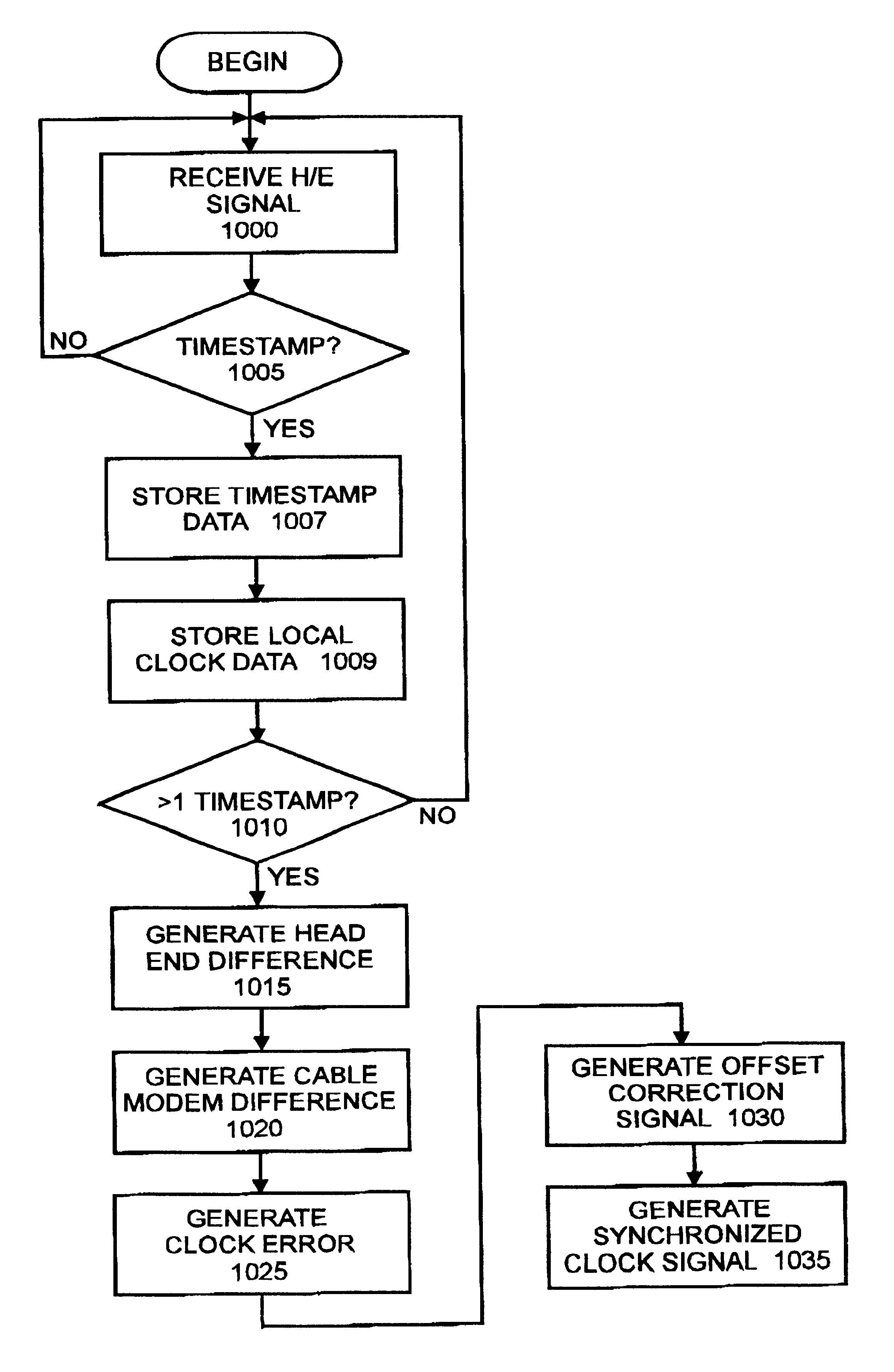
This invention avoids the analog approach of the VCXO entirely. For, in one embodiment the present invention synchronizes the clock of a local cable modem with that of the headend by following the basic method described below. Two successive timestamps are taken from the headend and compared to two local time samples from the local cable modem clock. These 4 measurements are used to compute an offset frequency that can be added or subtracted from the local clock to derive a new local clock frequency that is in perfect synchronization with the Headend. This is all done digitally, thus avoiding any non-idealities connected with analog hardware. Furthermore, no modification is required on the relatively inexpensive basic crystal oscillator typically used in cable modems. In one embodiment, the basic concept employs an architecture based on a numerically-controlled oscillator (NCO), of the type employed in direct-digital synthesizers (DDS). This concept is explained more fully below in ...


PUM


Abstract

A method and apparatus for time synchronization in a communications system such as a system including cable modems is provided. The synchronization method comprises the steps of receiving a first timestamp from a headend unit with the cable modem, and generating a first cable modem time reference with the cable modem in response to the receipt of the first timestamp. The cable modem then receives a second timestamp from the headend unit and generates a second cable modem time reference in response to the receipt of the second timestamp. A headend difference time comprising the difference of the first and second timestamps is then generated as is a cable modem difference time comprising the difference of the first and second cable modem time references. A clock error time that comprises the difference of the headend difference time and the cable modem difference time is then generated as well as a correction factor in response to the clock error time. The local clock of the cable modem is then synchronized with the master clock of the headend unit through the adjusting of the output of the local clock output in response to the correction factor. The correction factor in one instance comprises an offset value representative of the amount of clock error per local clock pulse. This offset value is added to an accumulator on each local clock pulse, and the local clock output is adjusted when the accumulator rolls over. The synchronized clock signal can then be utilized to determine a time slot in which the cable modem can transmit an upstream signal to the headend without colliding the upstream signal with upstream signals from other modems in the system.

Description

1. BACKGROUND OF THE INVENTIONa. Field of the InventionThe present invention relates to communication systems. In particular, the present invention relates to the synchronization of time signals amongst a plurality of communications system components such as cable modems.b. Description of Related ArtAs information becomes increasingly more available on communication networks such as a LAN or over the Internet, the development of new methods and apparatus for sending and receiving this information more quickly between communication system users has become an important issue. For instance, one-way and two-way cable modems, both internal and external, based on the Multimedia Cable Network System (MCNS) Data-Over-Cable Interface Specifications (DOCSIS) standard, are currently available to consumers to access data over the Internet at speeds far in excess of those previously attainable by standard analog telephone modems. An external cable modem is a complete, self contained unit which i...

Claims


Application Information

Patent Timeline
Patent Type & Authority Patents(United States)
IPC IPC(8): H04L12/56H04J3/06H04L12/28
CPCH04J3/0655H04L12/2801H04L47/28
Inventor BURNS, LAWRENCE M.BOYD, EDWARD
Owner HEWLETT PACKARD DEV CO LP
Why Eureka
Try Eureka