Optical connector

a technology of optical connectors and connectors, applied in the field of optical connectors, can solve the problems of large system, inability to replace worn ferrules or optical fibers, and inability to mount a plurality of optical connectors closer than the wall thickness, and achieve satisfactory mechanical strength and increase the effect of mounting density

Inactive Publication Date: 2002-09-17
HIROSE ELECTRIC GROUP
View PDF11 Cites 32 Cited by
  • Summary
  • Abstract
  • Description
  • Claims
  • Application Information

AI Technical Summary

Benefits of technology

Accordingly, it is an object of the invention to provide an optical connector which is made compact by incorporating a damping or filtering element and is able to be mounted in a large number closely to each other, thereby increasing the mounting density. In addition, the addition of the damping or filtering function is made by not increasing very much the number of components. Moreover, it is still another object of the invention to provide an optical connector that the worn ferrule or optical fiber can be replaced. It is yet another object of the invention to provide an optical connector which has satisfactory mechanical strength and a housing jacket resistant against electromagnetic interference.

Problems solved by technology

However, these conventional systems increase the distance between the optical connector and the adapter, resulting in the large systems.
Consequently, it must have a sufficiently thick wall to form such an opening so that it has been impossible to mount a plurality of optical connectors closer than the wall thickness.
The ferrules or optical fibers of optical connectors are worn out by abutting against mating optical connectors, but it has been impossible to replace the worn ferrules or optical fibers because they are fixed to the optical connectors.

Method used


Image

  • Optical connector
  • Optical connector
  • Optical connector

Examples


Embodiment Construction

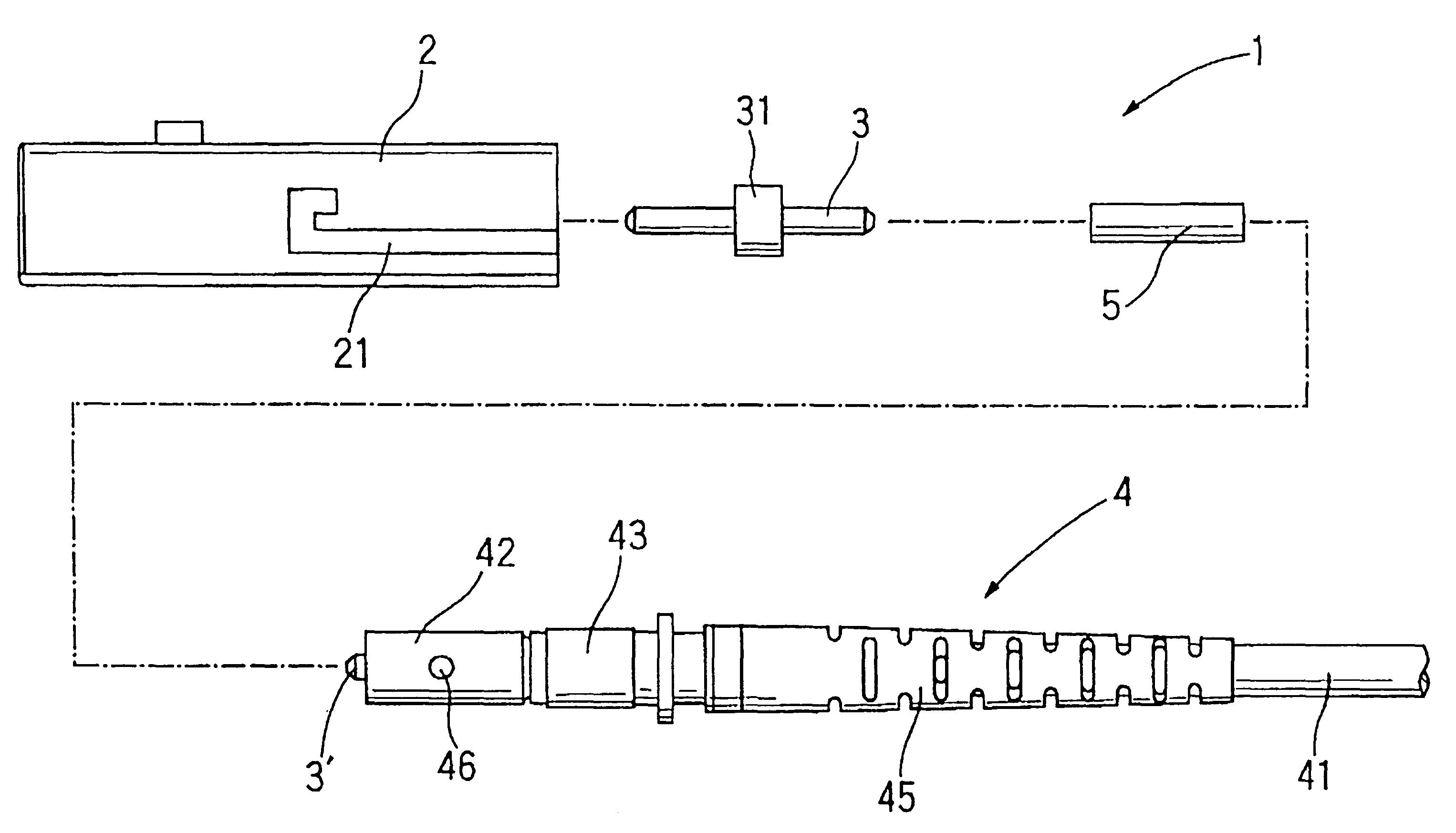
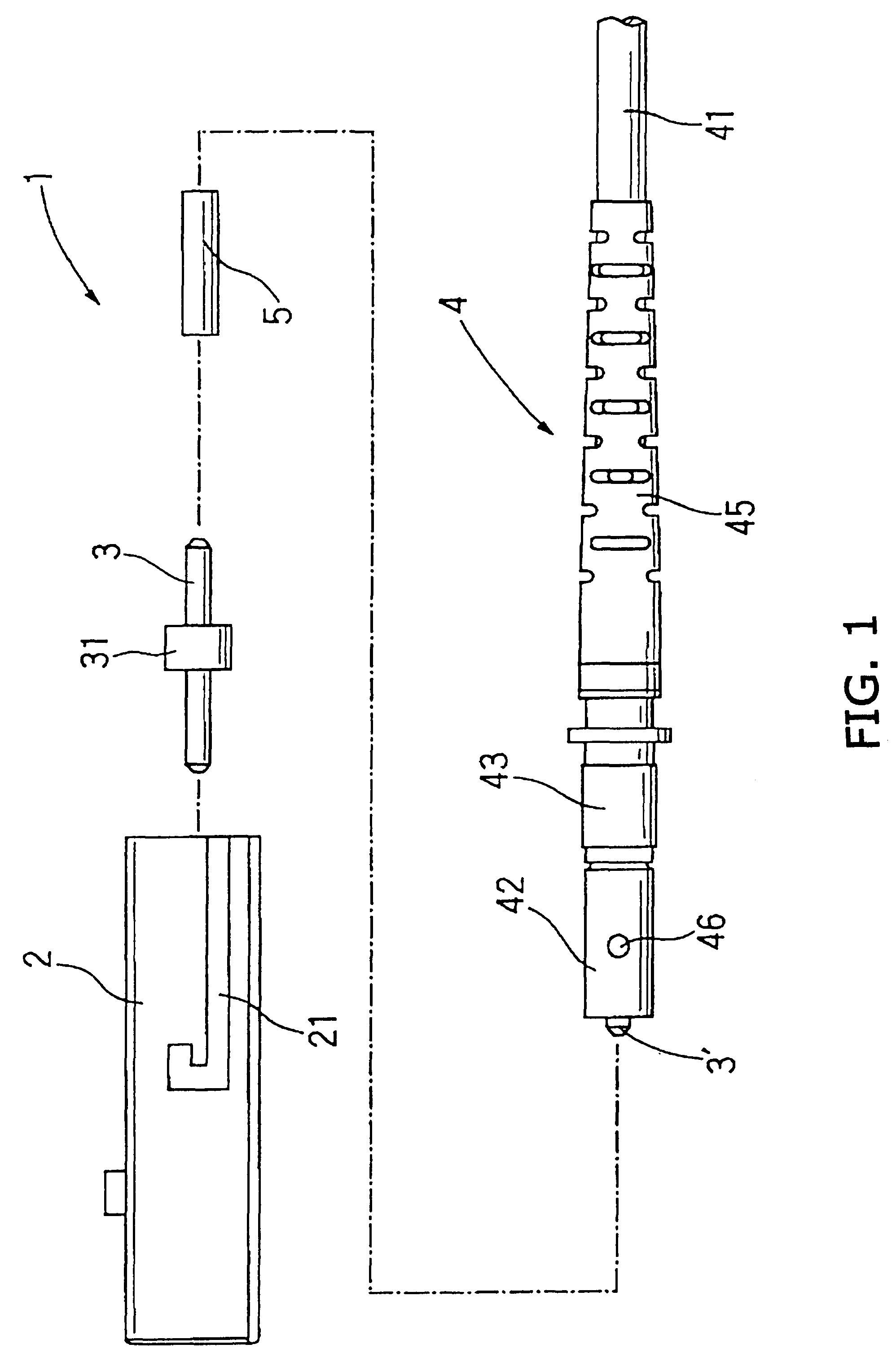
In FIG. 1, the optical connector 1 comprises a housing 2, a first ferrule 3, and a body section 4. These three sections are made easy to assemble and disassemble to permit replacement of the first ferrule 3.

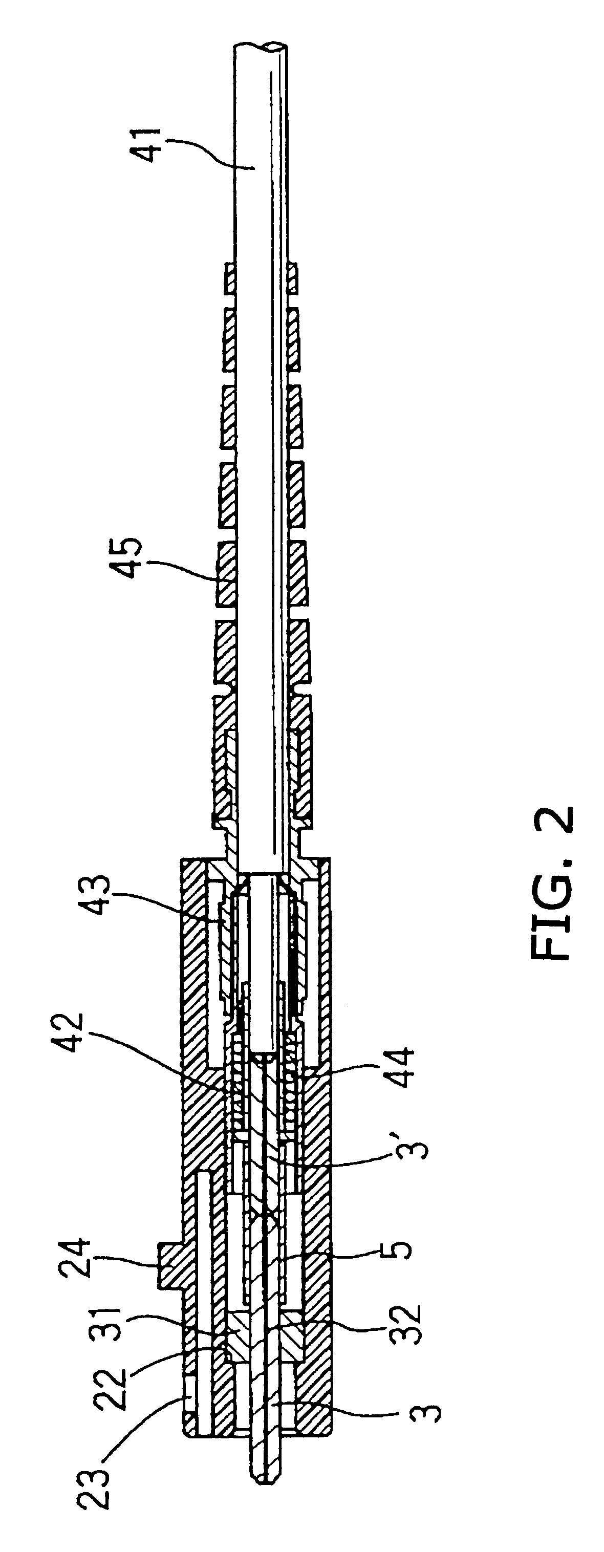
The body section 4 comprises a second ferrule section 3' cooperating with the first ferrule section 3 to form a ferrule and a aligning member or sleeve 5 for aligning the first and second ferrule sections 3 and 3' to form the ferrule. Alternatively, the aligning sleeve 5 may be replaced by the inner wall of the housing. Thus, the aligning member 5 is not limited to the sleeve.

The body member or section 4 further comprises an optical cable 41, a fixing metal 42 for fixing the optical cable 41, a crimping ring 43 for fixing the fixing metal 42 to the optical cable 41, a spring 44 provided within the fixing metal 42 to push the second ferrule section 3' and thus first ferrule section 3 toward the front tip of the optical connector, and a food 45 surrounding a front portion of the op...


PUM


Abstract

The optical connector comprising a housing (2), a first ferrule section (3) for holding an optical fiber having a damping or filtering function, a second ferrule section (3') for holding an ordinary optical fiber, and an aligning sleeve (5) for aligning the first and second ferrule sections (3, 3') for detachable abutment.

Description

BACKGROUND OF THE INVENTION1. Field of the InventionThe present invention relates to optical connectors and, particularly, to an optical connector capable of incorporating a damping or filtering element.2. Description of the Related ArtIn order to provide an optical connector with a damping or filtering function, it has been necessary to connect a separate damper or filter to the optical connector. The damper or filter is connected between the optical connector and an adapter, etc., to damp an optical signal or filter an optical signal of a predetermined frequency to the equipment.However, these conventional systems increase the distance between the optical connector and the adapter, resulting in the large systems. In addition, in order to be connected to the optical connector, the damper or filter must have the same opening as that of the adapter for receiving the optical connector. Consequently, it must have a sufficiently thick wall to form such an opening so that it has been imp...

Claims


Application Information

Patent Timeline
Patent Type & Authority Patents(United States)
IPC IPC(8): G02B6/26G02B6/38G02B6/00
CPCG02B6/266G02B6/3846G02B6/3845G02B6/389
Inventor MATSUMOTO, TATEOMO
Owner HIROSE ELECTRIC GROUP
Why Eureka
Try Eureka