
Multiprocessor system with fiber optic bus interconnect for interprocessor communications

a fiber optic bus and interconnection technology, applied in the field of multi-processor systems with fiber optic bus interconnection for inter-processor communications, can solve the problems of high probability of errors, additional packet latency, and problems that can be encountered

Inactive Publication Date: 2002-09-17
HEWLETT-PACKARD ENTERPRISE DEV LP
View PDF25 Cites 98 Cited by
  • Summary
  • Abstract
  • Description
  • Claims
  • Application Information

AI Technical Summary

Benefits of technology

A number of advantages are achieved by the present invention. First, using the communications link interconnect system of the present invention provides more flexibility as to the physical distance that may be allowed between processor units of a multiprocessing system. When processor units are contained in multiple cabinets, the present invention also provides more flexibility as to arrangement of those cabinets.
Further, the present invention permits mixing of different styles of processor units using interprocessor bus communications without concern for the electrical connections; that is, one style of processor unit can be coupled to another style of processor unit, for interprocessor communications, using the present invention without modifying both to achieve electrical compatibility on the intercommunication bus.

Problems solved by technology

It will be evident, however, that as the number of sections increases, increasing the average number of inter-section "hops" per packet, problems can be encountered, such as, for example, additional packet latency.
Obviously, manual system configuration is possible; however, system operators would most likely find this to be an awkward task, giving rise to the high probability of errors.
In addition, an operator most likely would not be able to quickly switch from one path to another between sections if any portion of a communication link 26 should fail.
First, when the system is powered up (or otherwise reset by software technique), each DDT 50 clears the memory locations of memory 50b containing the SCIs. A copy of the PCI, contained in the non-volatile memory 50a, is validated; that is, the valid bit is checked to see if it is TRUE. In addition, the ID portion is checked to ensure that the fiber optic interconnect unit has not been moved to a different section or bus since last power-up. If valid, autoconfiguration is enabled and a pair of configuration status packets are sent: one to the left neighbor, and one to the right neighbor. If the PCI is invalid, autoconfiguration is disabled, and it is not enabled until the PCI is updated to a valid value via the master MDS controller.
Second, when a configuration status packet is received, the receiving DDT 50 compares the information of "MY PCI" field 284 (what the sending DDT thought was the receiving DDTs PCI) with its PCI.
Thus, the process of disabling autoconfiguration system wide in this manner will "damage" the last automatically generated configuration.

Method used


Image

  • Multiprocessor system with fiber optic bus interconnect for interprocessor communications
  • Multiprocessor system with fiber optic bus interconnect for interprocessor communications
  • Multiprocessor system with fiber optic bus interconnect for interprocessor communications

Examples


Embodiment Construction

Overview:

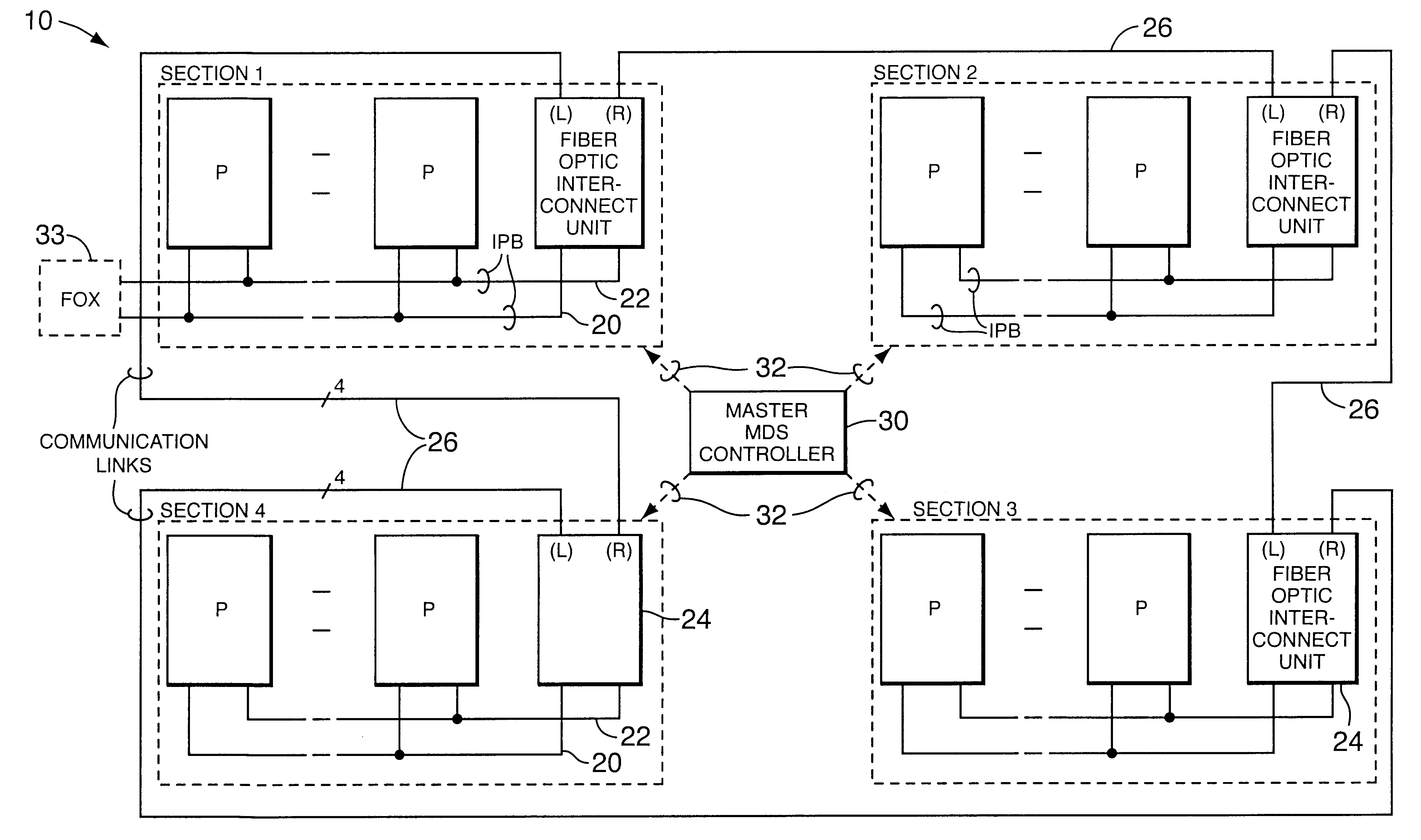
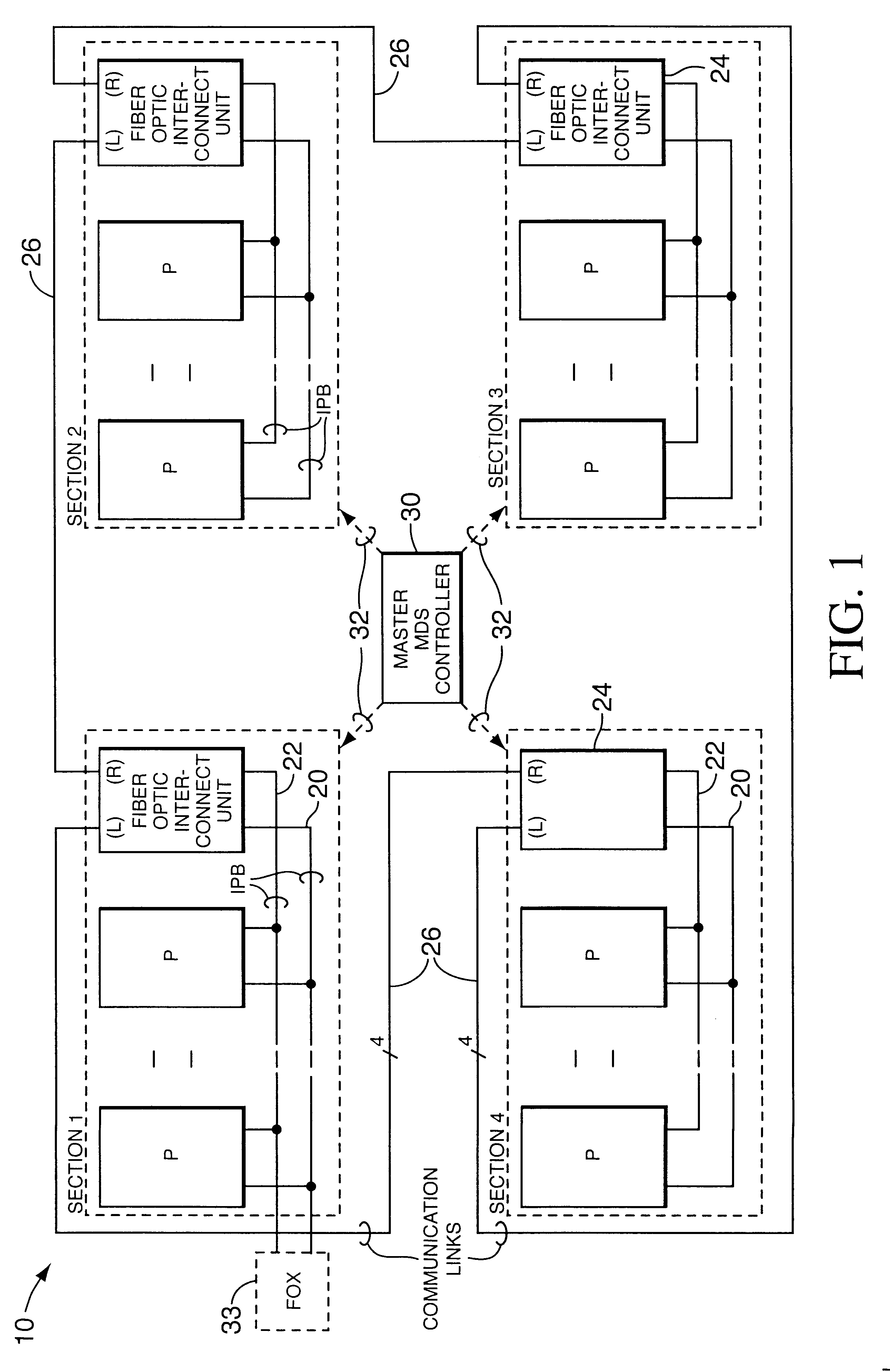
Referring first to FIG. 1, a multiprocessor system comprising a number of individual processor units (P) are shown as being arranged in four "sections," 1, . . . ,4. Within each of those sections 1, . . . ,4, are preferably at least two processor units (P) coupled to one another by preferably a pair of interprocessor buses (IPB) 20, 22 for processor to processor communication. Processor unit and bus pairs are preferred for implementing a fault tolerant philosophy, but that philosophy is not necessary to the present invention.

The IPBs 20, 22 are generally constructed and operated as taught by U.S. Pat. Nos. 4,224,496 and 4,888,684, whose teachings are incorporated herein by reference to the extent necessary. Each IPB 20, 22 is composed of multiple signal lines for carrying parallel bits of data, control signals, and the like.

Also within each of the sections 1, . . . ,4 is a fiber optic interface unit 24 that connects the IPBs 20, 22 to a communications link 26.

Preferably, th...


PUM


Abstract

In a data processing system of the type having multiple processor units coupled to one another by a bus means for interprocessor communications there is provided a fiber optic interconnection system to interconnect the bus means of multiple processor sections to one another, thereby allowing groups of the processor units to be physically spaced from one another. The fiber optic interconnect system includes, for each multiprocessor unit section functions to receive messages communicated on the interprocessor bus of that section for receipt by a destination processor of the other section, format the message for fiber optic transmission, and transmit the message; and circuitry for receiving messages on the fiber optic link, scheduling the message for transmission to the destination processor, and maintaining that scheduling in the face of receipt of another message for the same processor unit. The fiber optic interconnect system includes means for configuring the system to identify which processor units are in which section and, when more than two sections are interconnected by the fiber optic link, provide information as to the shortest route to the destination processor from a section.

Description

The present invention is directed generally to data processing, and more particularly to data processing systems in the form of multiple processor units interconnected to one another by an bus means for interprocessor communication therebetween. More particularly, the invention is directed to a data processing system in which groups or sections of processors are coupled to one another by a communications link that routes messages from one processor in one section to another processor in another section.An increasingly popular type of data processing system is one implemented with a number of individual processor units capable of operating either individually or in parallel to perform data processing tasks. This type of processing system differentiates from a network of interconnected processing systems by the fact that the individual processor units are interconnected by a bus dedicated to interprocessor communication. Examples of this form of processing system may be found in U.S. ...

Claims


Application Information

Patent Timeline
Patent Type & Authority Patents(United States)
IPC IPC(8): H04L12/56
CPCH04L45/06
Inventor SARNIKOWSKI, SCOTTAGARWALA, UNMESHQUAN, STANLEY S.COMSTOCK, CHARLES E.MOORE, FRANK G.
Owner HEWLETT-PACKARD ENTERPRISE DEV LP
Learn More