
Fuel reformer and fuel reforming method

a technology of fuel reformer and reformer, which is applied in the direction of automatic ignition control, process and machine control, instruments, etc., can solve the problems of large size of the reformer, long time required, and large quantity of energy

Inactive Publication Date: 2002-09-24
TOYOTA JIDOSHA KK
View PDF13 Cites 24 Cited by
  • Summary
  • Abstract
  • Description
  • Claims
  • Application Information

AI Technical Summary

Benefits of technology

With the reformer according to the present invention, by setting the maximum capacity of the shift reaction section in a predetermined ratio to the maximum capacity of the reforming section, the shift reaction section can be made compact. As a result, the energy required to increase the temperature of the shift reaction section at start-up can be reduced and at the same time the required period of time can be shortened. Moreover, because the shift reaction section is compact, the reduction in efficiency when operating the fuel reformer at a region much smaller than the maximum capacity of the reforming section can be prevented, thereby improving the overall efficiency of the reformer.
Alternatively, the fuel reformer according to the present invention further comprises a carbon monoxide concentration sensor for detecting ct, the carbon monoxide concentration, in the hydrogen-rich gas after the reaction at the shift reaction section, wherein the control means determines whether the hydrogen-rich gas supplied to the shift reaction section exceeds the maximum capacity of the shift reaction section based on the carbon monoxide concentration detected by the carbon monoxide concentration sensor. In this manner, the carbon monoxide concentration in the hydrogen-rich gas after the reaction at the shift reaction section can be controlled with high precision. In this aspect of the fuel reformer, the control means can control the oxidation gas supplier to make the carbon monoxide concentration detected by the carbon monoxide concentration sensor less than a predetermined value. In this manner, the carbon monoxide concentration in the hydrogen-rich gas after the reaction at the shift reaction section can be reduced to a value less than a predetermined concentration.
In this fuel reforming method according to the present invention, when supplied amount of the hydrogen-rich gas does not exceed the capacity of the reaction layer used for step (b), percentage of hydrogen present in the hydrogen-rich gas is increased by the shift reaction represented by equation 2 in step (b), and when supplied amount of the hydrogen-rich gas exceeds the capacity of the reaction layer used for step (b), oxidation gas is mixed with the hydrogen-rich gas, oxidizing a portion of carbon monoxide present in the hydrogen-rich gas, thereby reducing the percentage of carbon monoxide present in the hydrogen-rich gas. As a result, the reaction layer used for step (b) can be made compact, and the required energy and time to increase the temperature of the reaction layer used for step (b) can be reduced. Furthermore, because the reaction layer used for step (b) is compact, the reduction in the efficiency which occurs when fuel is reformed in a region much lower than the maximum capacity of the reaction layer used for step (a) can be prevented, and the overall efficiency of the reformer can be improved.

Problems solved by technology

However, in these conventional reformers, the shift reaction section is required to have a maximum capacity corresponding to the maximum capacity of the reforming section in order to sufficiently perform the shift reaction represented by equation 2, causing the size of the reformer to be large.
This increase in size of the reformer causes problems in which a large quantity of energy and a long period of time are required to sufficiently increase the temperature of the shift reaction section at the time of start-up.
In addition, the increase in size of the reformer causes another problem that the efficiency is reduced when the reformer is operating in a region much less than the maximum capacity.

Method used


Image

  • Fuel reformer and fuel reforming method
  • Fuel reformer and fuel reforming method
  • Fuel reformer and fuel reforming method

Examples


Embodiment Construction

)

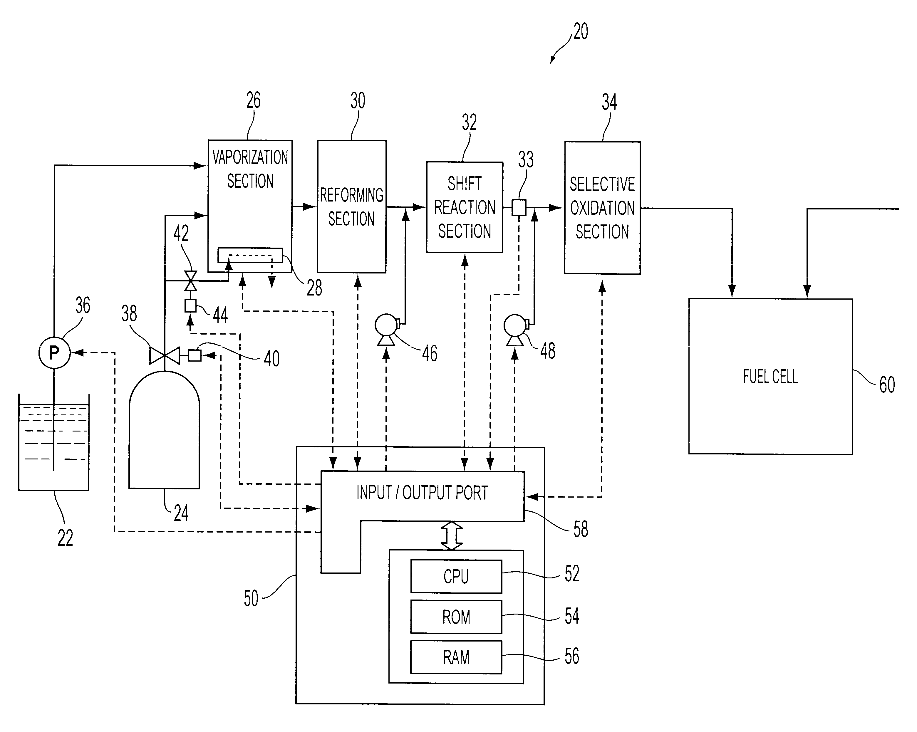
The preferred embodiment of the present invention is described hereinafter. FIG. 1 schematically shows a fuel reformer 20 according to one embodiment of the present invention. As shown, the fuel reformer 20 is connected to a fuel cell 60, and the fuel cell 60 generates electric power by receiving supply of reformed fuel gas from the fuel reformer 20.

The fuel reformer 20 has a vaporization section 26 for vaporizing water supplied from a water tank 22 and mixing vaporized water and natural gas having methane as its primary constituent, supplied from a natural gas tank 24, a reforming section 30 for reforming the natural gas mixed with the water vapor to hydrogen-rich gas containing hydrogen, a shift reaction section 32 for reforming the shift reaction represented by equation 2 on the carbon monoxide present in the hydrogen-rich gas, a selective oxidation section 34 for selectively oxidizing carbon monoxide which were not shifted by the shift reaction section 32, and an electric contr...


PUM

PropertyMeasurementUnit
molar ratioaaaaaaaaaa
temperatureaaaaaaaaaa

Abstract

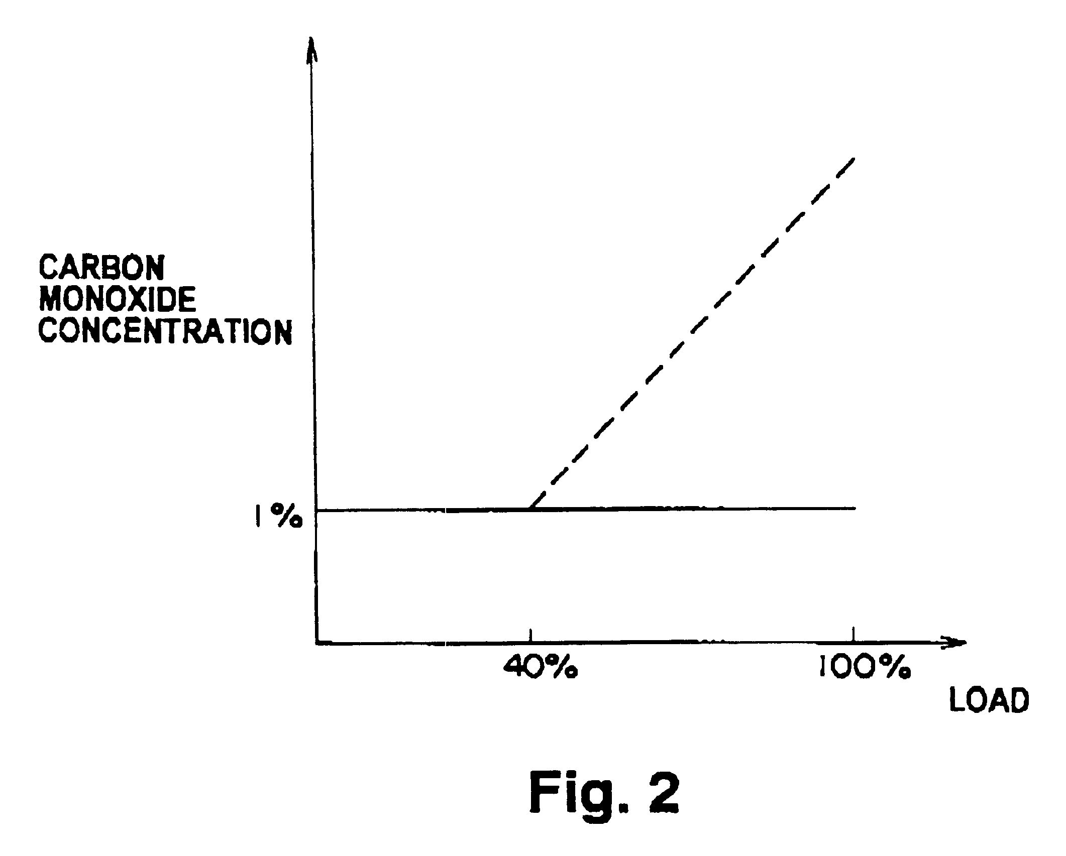
A shift reaction section 32 is designed to have a maximum capacity of about 40% of the maximum capacity of reforming section 30. When hydrogen-rich gas is supplied to the shift reaction section 32 in excess of its maximum capacity, a blower 46 supplies air to the hydrogen-rich gas in an amount corresponding to the supply of hydrogen-rich gas, and oxidation reaction of carbon monoxide is performed in addition to the shift reaction. By controlling the amount of air supplied, the carbon monoxide concentration at the exit of the shift reaction section 32 is maintained at a concentration less than a predetermined value. As a result, a fuel reformer 20 can be made compact, and at the same time, the energy required to increase the temperature at the time of start up can be reduced.

Description

1. Field of the InventionThe invention generally relates to a fuel and fuel reforming method, and in particular, to a fuel reformer for reforming hydrocarbon fuel to hydrogen-rich fuel and a fuel reforming method for reforming hydrocarbon fuel to hydrogen-rich fuel.2. Description of the Prior ArtConventionally, a type of reformer has been proposed which has a reforming section and a shift reaction section (for example, Japanese Patent Laid-Open Publication No. Hei 6-24702). In the reforming section, methanol is reformed to hydrogen-rich gas by reacting at a temperature between 300 and 400.degree. C., and in the shift reaction section, carbon monoxide in the hydrogen-rich gas, reformed at the reforming section, is reacted at a temperature between 200 and 300.degree. C. to increase the percentage of hydrogen present in the hydrogen-rich gas. When methanol is reformed to hydrogen-rich gas by the following equations 1 and 2, the reaction represented by equation 1 is an endothermic react...

Claims


Application Information

Patent Timeline
Patent Type & Authority Patents(United States)
IPC IPC(8): C01B3/48C01B3/32C01B3/00C01B3/58C01B3/34H01M8/04H01M8/06
CPCC01B3/323C01B3/48C01B3/583C01B2203/0233C01B2203/0283C01B2203/044C01B2203/047C01B2203/0811C01B2203/1052C01B2203/1076C01B2203/1241C01B2203/1276C01B2203/1288C01B2203/16C01B2203/1604C01B2203/1619C01B2203/1661C01B2203/1671C01B2203/169C01B2203/1695
Inventor AOYAMA, SATOSHIARAKI, YASUSHI
Owner TOYOTA JIDOSHA KK
Learn More