
System and method for recovering a pilot tone in a local multipoint distribution system signal

a multi-point distribution and signal recovery technology, applied in the field of electronic signal processing, can solve the problems of high cost of oscillator for maintaining stable frequency, difficult fabrication of saw filter, and high cost of customer premises equipment, and achieve the effect of improving the signal to noise ratio of the received pilot ton

Inactive Publication Date: 2002-09-24
RAYTHEON CO
View PDF4 Cites 7 Cited by
  • Summary
  • Abstract
  • Description
  • Claims
  • Application Information

AI Technical Summary

Benefits of technology

From the foregoing, it may be appreciated that a need has arisen for an effective and efficient pilot tone recovery system. In accordance with the present invention, an improved system and method for recovering a pilot tone in an LMDS signal are provided which substantially eliminate or reduce disadvantages and problems associated with conventional pilot tone recovery systems.
The present invention provides various technical advantages over conventional pilot tone recovery systems. For example, one technical advantage is providing an improved system and method for recovering a pilot tone in an LMDS signal. In particular, the pilot tone recovery system utilizes components capable of fabrication on a monolithic integrated circuit. In addition, the pilot tone recovery system improves the signal to noise ratio of the received pilot tone. Other technical advantages may be readily apparent to one skilled in the art from the following figures, description, and claims.

Problems solved by technology

The head end, or node, has very expensive oscillators for maintaining stable frequencies.
The customer premises equipment needs lower cost equipment which generally cannot maintain a stable frequency.
SAW filters can be expensive and difficult to fabricate.
In addition, SAW filters cannot be formed on a monolithic integrated circuit.

Method used


Image

  • System and method for recovering a pilot tone in a local multipoint distribution system signal
  • System and method for recovering a pilot tone in a local multipoint distribution system signal
  • System and method for recovering a pilot tone in a local multipoint distribution system signal

Examples


Embodiment Construction

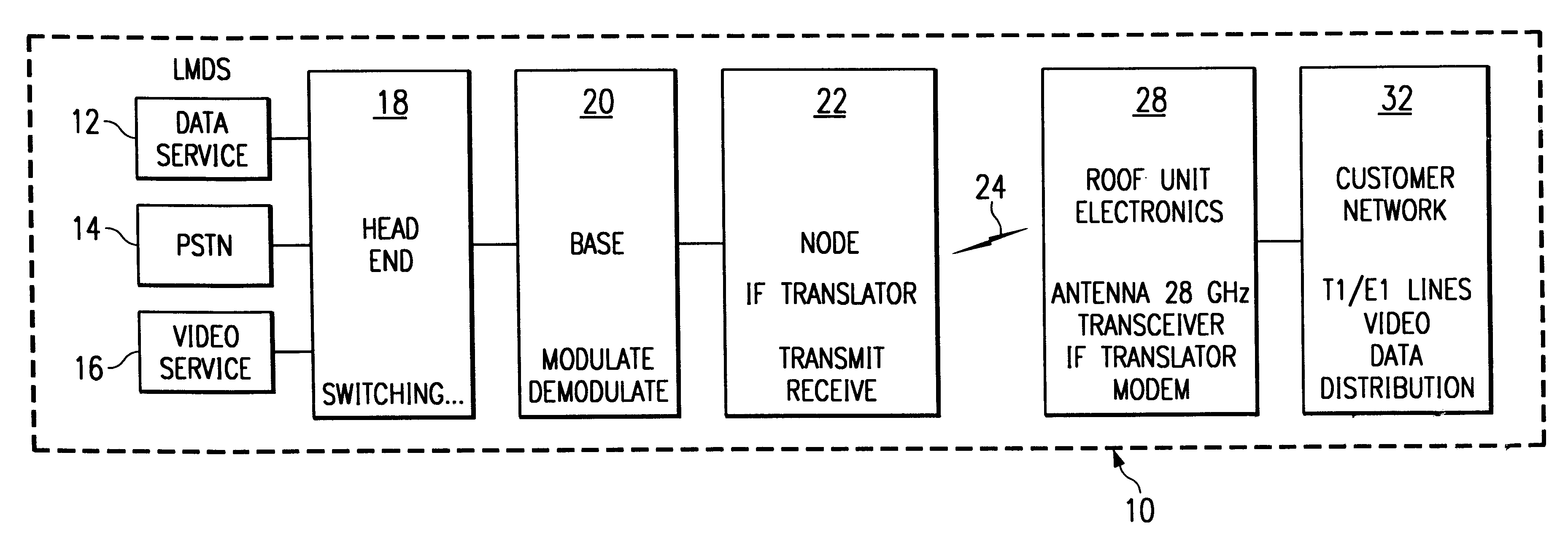
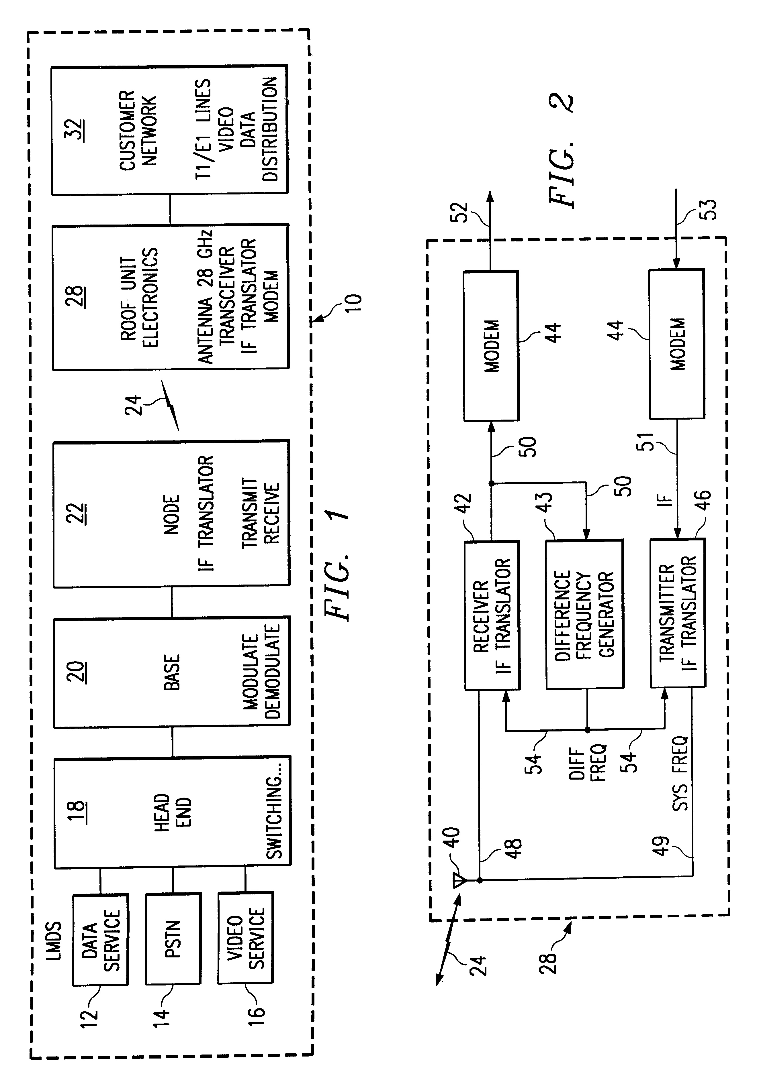
Referring to FIG. 1, a Local Multipoint Distribution System (LMDS) is generally indicated at 10. LMDS 10 provides a data service 12, a telephone service 14, and a video service 16 through radio frequency communications at a system frequency. LMDS 10 may be assigned a system frequency in the range of approximately 10 GHz to 40 GHz. In one embodiment, the system frequency is 27.36 GHz. Data service 12 may be any suitable data service such as an Internet connection. Telephone service 14 may include providing a customer with a wireless connection to the public switched telephone network. Video service 16 may include local broadcast television stations, satellite broadcast stations, and any other suitable video source. LMDS 10 may provide any service suitable for transmission and reception over a wireless connection.

Data service 12, telephone service 14, and video service 16 are coupled to a head end 18. Head end 18 provides initial switching for telephone service 14 and allocation of vi...


PUM


Abstract

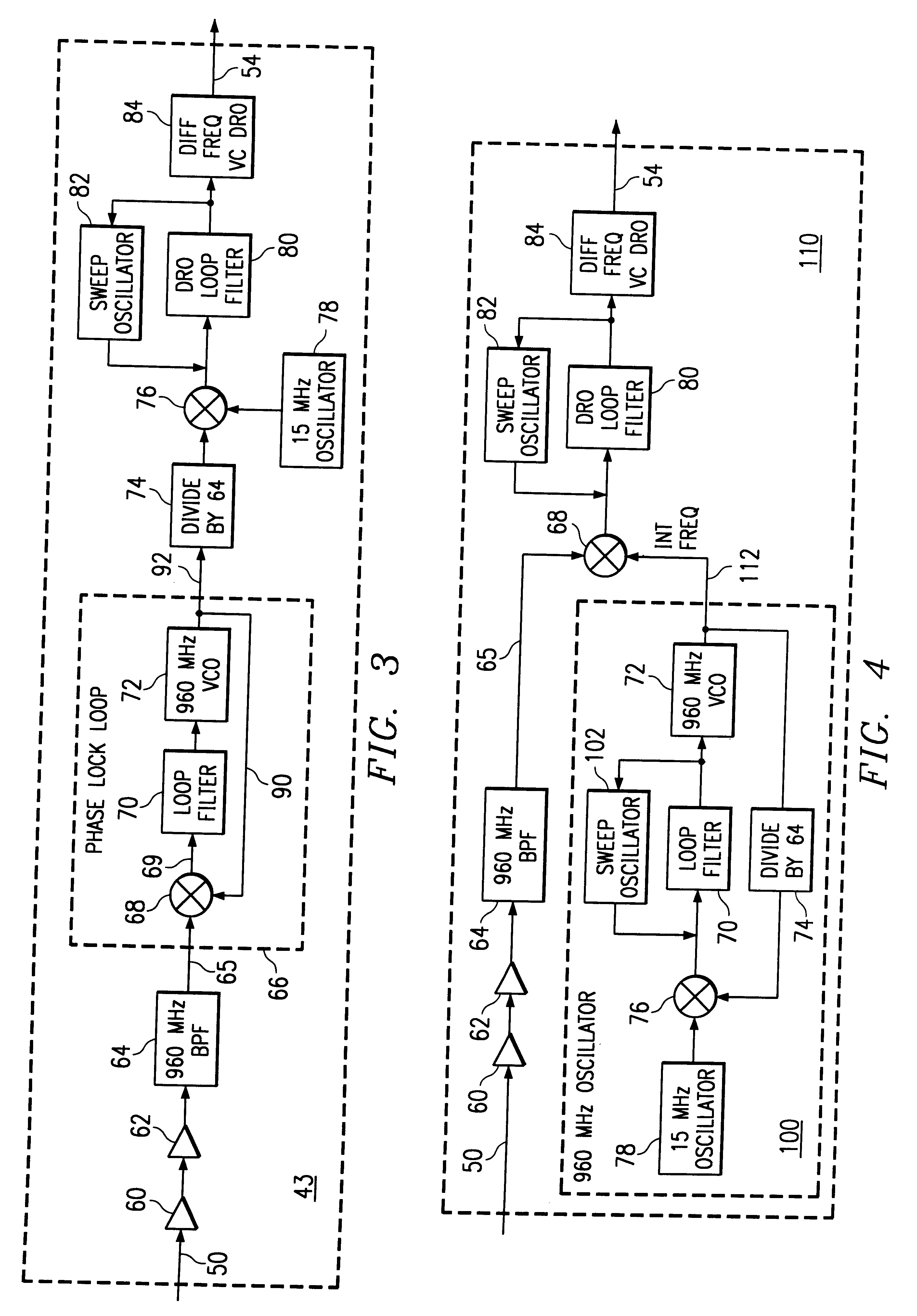
An intermediate frequency signal (50) is received by a difference frequency generator (43). The intermediate frequency signal (50) includes a pilot tone frequency. A band pass filter (64) removes frequencies surrounding the pilot tone frequency. A phase lock loop (66) generates a pilot tone signal from the pilot tone frequency. A divisor (74) divides the frequency of the pilot tone signal by a specified number. A second phase detector (76) determines a frequency difference between the pilot tone signal and a stable frequency signal generated by a stable frequency oscillator (78). A control voltage for a difference frequency voltage controlled dielectric resonant oscillator (84) is adjusted based on the frequency difference. A system frequency signal (48) is downconverted to an intermediate frequency signal (50) using a difference frequency signal (54).

Description

TECHNICAL FIELD OF THE INVENTIONThis invention relates in general to the field of electronic signal processing and more particularly to a system and method for recovering a pilot tone in a local multipoint distribution system signal.BACKGROUND OF THE INVENTIONA Local Multipoint Distribution System (LMDS) is a point to multipoint radio frequency communication system. It operates in the United States using frequency bands between 26 GHz and 29 GHz. The specific frequencies assigned to LMDS varies by country and is generally in the 10 GHz to 40 GHz frequency range. The frequency range set aside for LMDS requires a line of sight between the transmitting device and receiving device. LMDS may be used to provide and distribute telecommunication services, data communication services, and video services.The LMDS head end and customer premises operate on an intermediate frequency. The intermediate frequency allows existing modems to communicate with digital electronic devices. Prior to transm...

Claims


Application Information

Patent Timeline
Patent Type & Authority Patents(United States)
IPC IPC(8): H03J7/02H03J7/18H03J7/06H03J7/28H04L27/00
CPCH03J7/065H03J7/285H04L2027/0022H04L2027/0055H04L2027/0087
Inventor BLACK, MICHAEL F.
Owner RAYTHEON CO
Learn More