In-situ deep remediation injection system and method

a deep remediation and in-situ technology, applied in water cleaning, soil conditioning compositions, chemistry apparatuses and processes, etc., can solve the problems of high equipment requirements, high cost, and high equipment requirements, and achieve the effect of improving the quality of soil and ground water

Inactive Publication Date: 2002-10-01
NICKELL JERRY D
View PDF0 Cites 60 Cited by
  • Summary
  • Abstract
  • Description
  • Claims
  • Application Information

AI Technical Summary

Benefits of technology

In accordance with another preferred aspect of the invention, the deep remediation injection system further comprises an adapter tube between the shaft portion and the fluid injection portion, the adapter tube having an upper end including a plurality of co-axial O-rings and being adapted for co-axial insertion into the first conduit in the shaft, and a lower end including a plurality of co-axial O-rings and being adapted for co-axial insertion into a conduit in the fluid injection portion, thereby permitting flow of fluid from the first conduit to the lower set of injection ports and sealable separation of the fluid from fluid in the second conduit leading to the upper set of injection ports.

Problems solved by technology

This type of remediation is a very expensive system and very cumbersome and required large equipment.
This type of remediation system also does not provide a fine adjustment of the remediation process because it relies upon a few large holes and not many small ones to tightly control the treatment area.
This use of drilled holes and set casing also required large drilling equipment to make the holes and large pipe handling equipment to set the pipe in the holes.
This has been a very expensive process for remediation and cost is a very important factor in the remediation business.
It also can have the pollution side effect of vapor and air pollution while the soil is being removed and moved to the incineration site if not controlled, but the control adds cost to the process also.
This approach has many pollution problems such as possible water pollution and air pollution, and is also very expensive.
Most of the prior art was and is designed and used in solo applications and does not work with the other remediation techniques.
Although this approach has advantages over the other prior art approaches, the disclosed soil penetrating lance and the method for using it has been found to have drawbacks.
Because U.S. Pat. No. 5,868,523 is adapted only for injection of one liquid stream at a time, intimate mixing of the hydrogen peroxide and the catalyst-containing liquid in the soil in the optimum proportion cannot be assured.
However, spacing the sets of ports far apart also diminishes the intimacy of the mixing of the gas and / or liquids discharged into the soil from the respective sets of ports.
It has been found, however, that this beveled sealing face arrangement may permit leakage between the air conduit and the liquid conduit.

Method used


Image

  • In-situ deep remediation injection system and method
  • In-situ deep remediation injection system and method
  • In-situ deep remediation injection system and method

Examples


Embodiment Construction

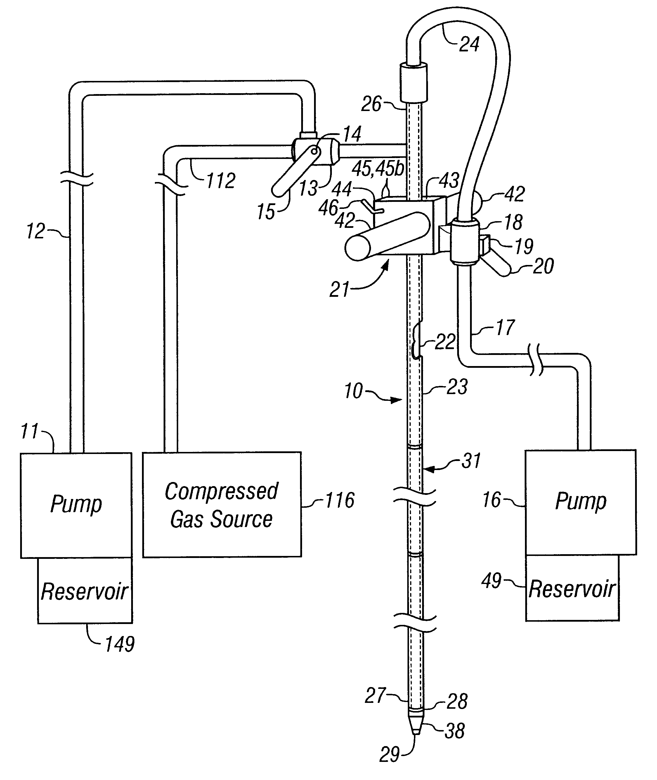
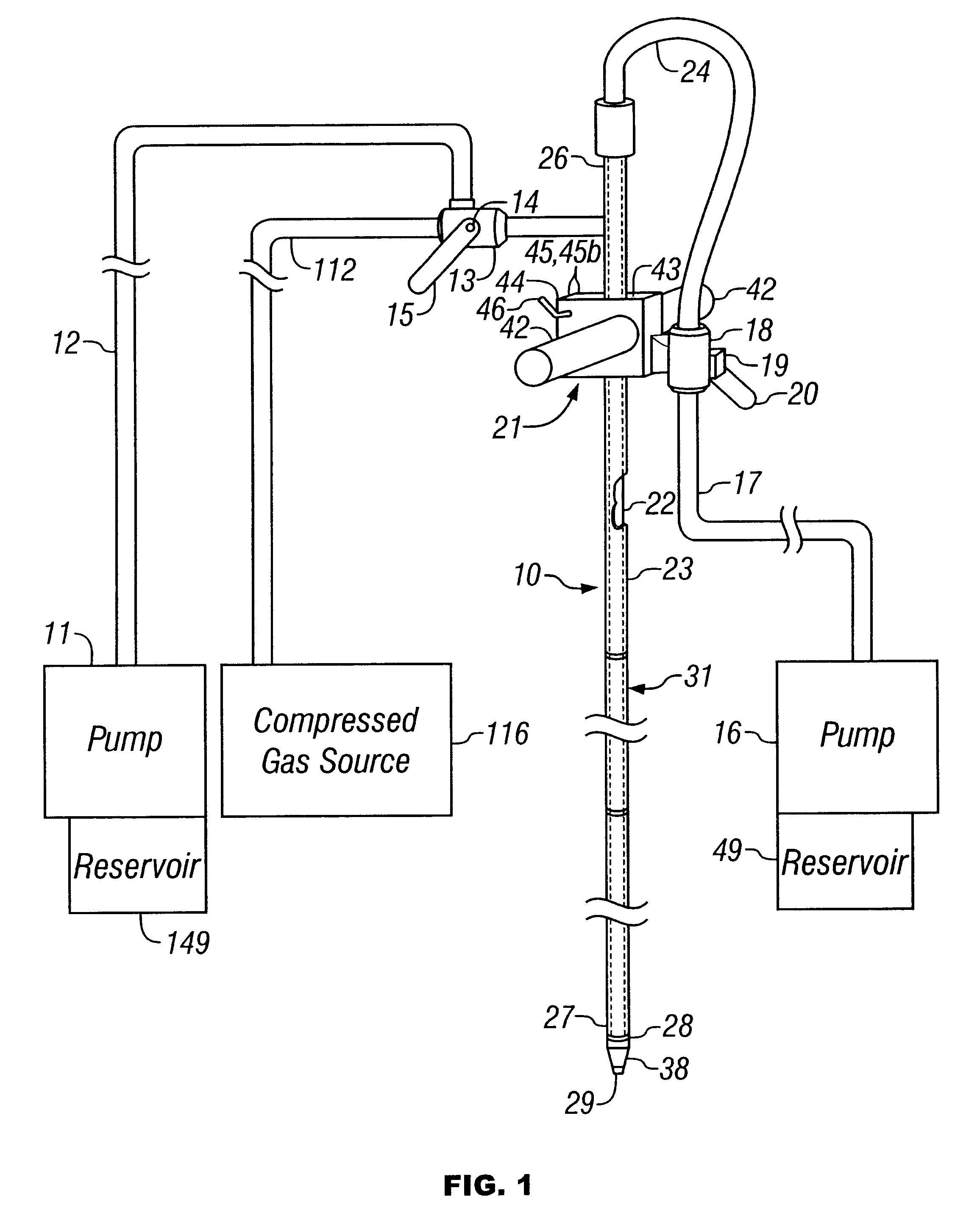
Referring now to FIG. 1, the general reference 10 shows the soil penetrating lance of this invention connected in fluid communication to a liquid pump 11 for pumping a first liquid from reservoir 149 to one end 26 of the soil penetrating lance 10. The connection is through tube 12 to a three-way connector valve 13, which has a selector valve handle 14. The selector valve handle 14 is operable to allow the operator to selectably open and close the flow of the pressurized liquid from the pump 11 to the soil penetrating lance 10 or, alternatively, to selectively open and close the flow of a compressed gas such as air, ozone, nitrogen or oxygen from source 116 through tube 112. Connection valve 13 is constructed so as to permit selection of one of the fluid streams through either tube 12 or 112, but not both at the same time. The first liquid preferably includes a treatment substance such as dissolved oxygen or ozone, hydrogen peroxide, surfactant, a catalyst such as iron sulfate or pot...


PUM


Abstract

An improved deep remediation injection system for in-situ remediation of contaminated soil and ground water. The system includes a soil penetrating lance for injecting at least two different highly-pressurized fluids taken from the group of air, gaseous oxygen, ozone, oxygenated liquid, hydrogen peroxide, surfactant-containing liquid, catalyst-containing liquid and suspended biologicals-containing liquids, or a liquid containing other chemicals, into said contaminated soil as said soil penetrating lance is inserted for penetration therein. The soil penetrating lance has at least an upper set of injection ports, the upper set of injection ports being generally radially spaced-apart on said lance, and at least one lower set of injection ports, the lance having an average width in the vicinity of the upper set of injection ports. The lance further includes substantially fluidically-independent first and second conduits leading, respectively, to the lower set of injection ports and the upper set of injection ports so as to permit delivery of separate pressurized fluid streams to the upper and lower sets of injection ports and then into the soil. The upper and lower sets of injection ports are spaced apart from each other on said lance a distance no farther than about three times the average width of said lance in the vicinity of the upper set of injection ports.

Description

This invention relates to deep remediation injection systems for in-situ remediation of contaminated soil and ground water by progressive penetration both vertically and horizontally in contaminated soil and ground water using treatment liquids under high pressure and low volume.The prior art's use of biologicals and other treatment materials for soil and water remediation is well-developed but the means of delivery varied widely. For example, some applications have used large boring devices to drill holes in the contaminated soil and set casing into the hole but leave the hole open at the bottom to receive the treatment biologicals for biological remediation. This type of remediation is a very expensive system and very cumbersome and required large equipment. This type of remediation system also does not provide a fine adjustment of the remediation process because it relies upon a few large holes and not many small ones to tightly control the treatment area. This use of drilled hol...

Claims


Application Information

Patent Timeline
Patent Type & Authority Patents(United States)
IPC IPC(8): B09C1/10B09C1/00B09C1/08
CPCB09C1/00B09C1/08B09C1/10B09C2101/00Y10S588/90
Inventor NICKELL, JERRY D.
Owner NICKELL JERRY D
Why Eureka
Try Eureka