Dual-element 3-way compact fluorescent lamp

a fluorescent lamp and compact technology, applied in the direction of discharge tube luminescnet screen, transit tube circuit elements, cathode-ray/electron beam tube circuit elements, etc., can solve the problems of excessively large, bulky inefficient assembly, and high manufacturing cost of compact bulbs, so as to achieve less maintenance, greater initial cost of fluorescent lamps, and less effor

Inactive Publication Date: 2002-10-01
TECHNICAL CONSUMER PROD INC AN OHIO CORP
View PDF11 Cites 22 Cited by
  • Summary
  • Abstract
  • Description
  • Claims
  • Application Information

AI Technical Summary

Benefits of technology

The present invention relates to a compact 3-way fluorescent lamp that is designed to serve as a replacement for a 3-way incandescent bulb. Even though the initial cost of a fluorescent lamp is greater than an incandescent bulb, a 3-way fluorescent lamp is advantageous for use because an 11 / 22 / 33 watt fluorescent lamp produces the same illumination equivalent to a 50 / 100 / 150 incandescent bulb and is more efficient to operate. In addition, there is less maintenance since it does not have to be replaced as frequently as the incandescent bulb because of its enhanced longevity.
It is still yet a further object of the present invention to provide a novel compact 3-way fluorescent lamp that utilizes an EMI filter to reduce the electromagnetic interference caused by the switching of the MOSFETs.

Problems solved by technology

Up to now, these attempts have been hampered by lagging technologies that made large bulky inefficient assemblies that were expensive to manufacture and quite cumbersome at best.
Electromagnetic ballasts, ones which were the predecessors to the electronic ballasts, had the disadvantage of being heavy because of the metal core, failed when overheated because of insufficient cooling and heat-sinking, and were excessively large when compared to a compact bulb itself.
If one were to consider the development of a 3-way triple biaxial fluorescent lamp using electromagnetic ballasts, a rather unwieldy assembly would evolve.
A lamp of this type could have been manufactured only by extremely complex manufacturing processes.
However, neither teaches of being designed for use as 3-way replacement lamps.

Method used


Image

  • Dual-element 3-way compact fluorescent lamp
  • Dual-element 3-way compact fluorescent lamp
  • Dual-element 3-way compact fluorescent lamp

Examples


Embodiment Construction

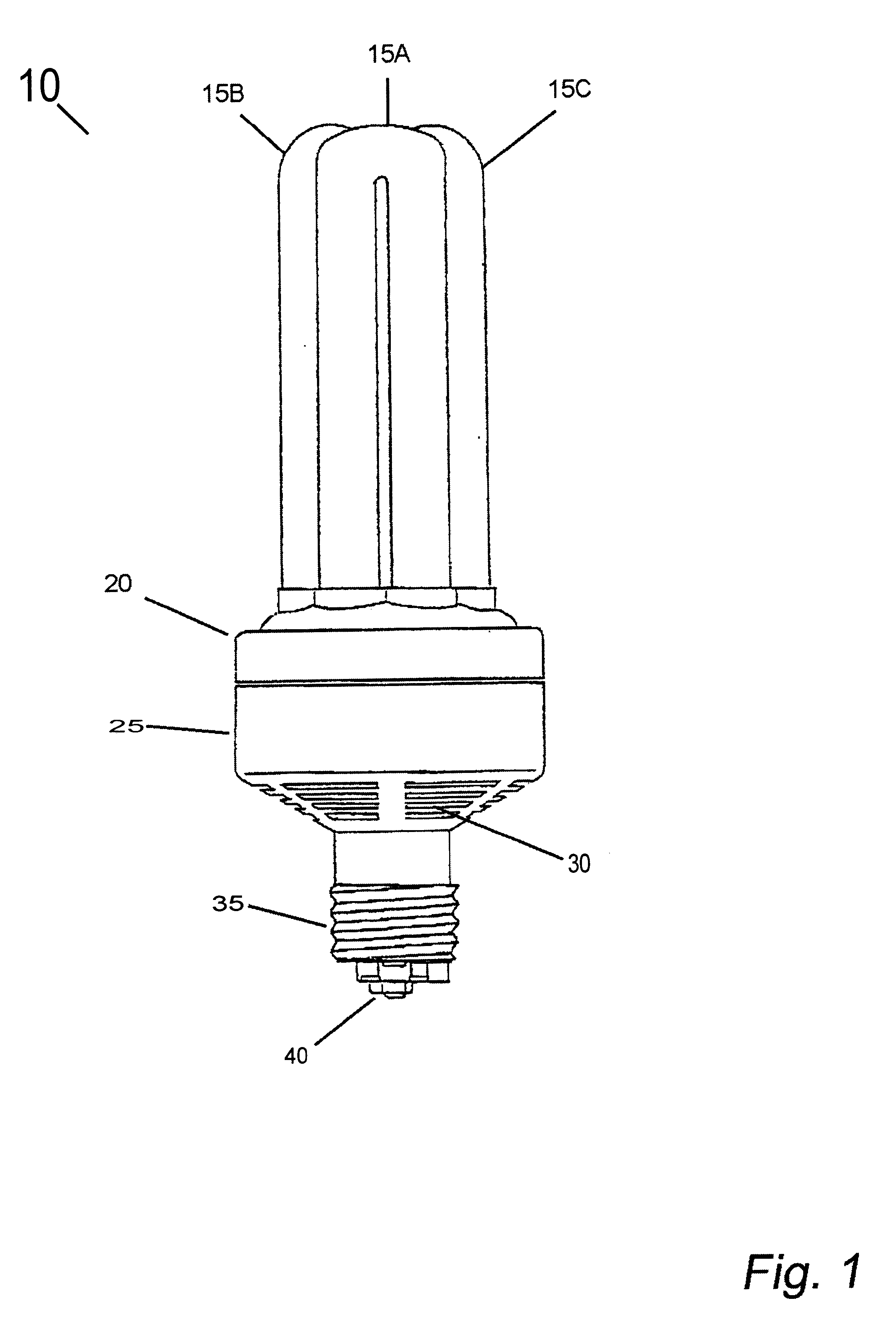
The present invention relates primarily to a compact dual element 3-way fluorescent lamp that is designed for use as a direct replacement for a 3-way incandescent bulb.

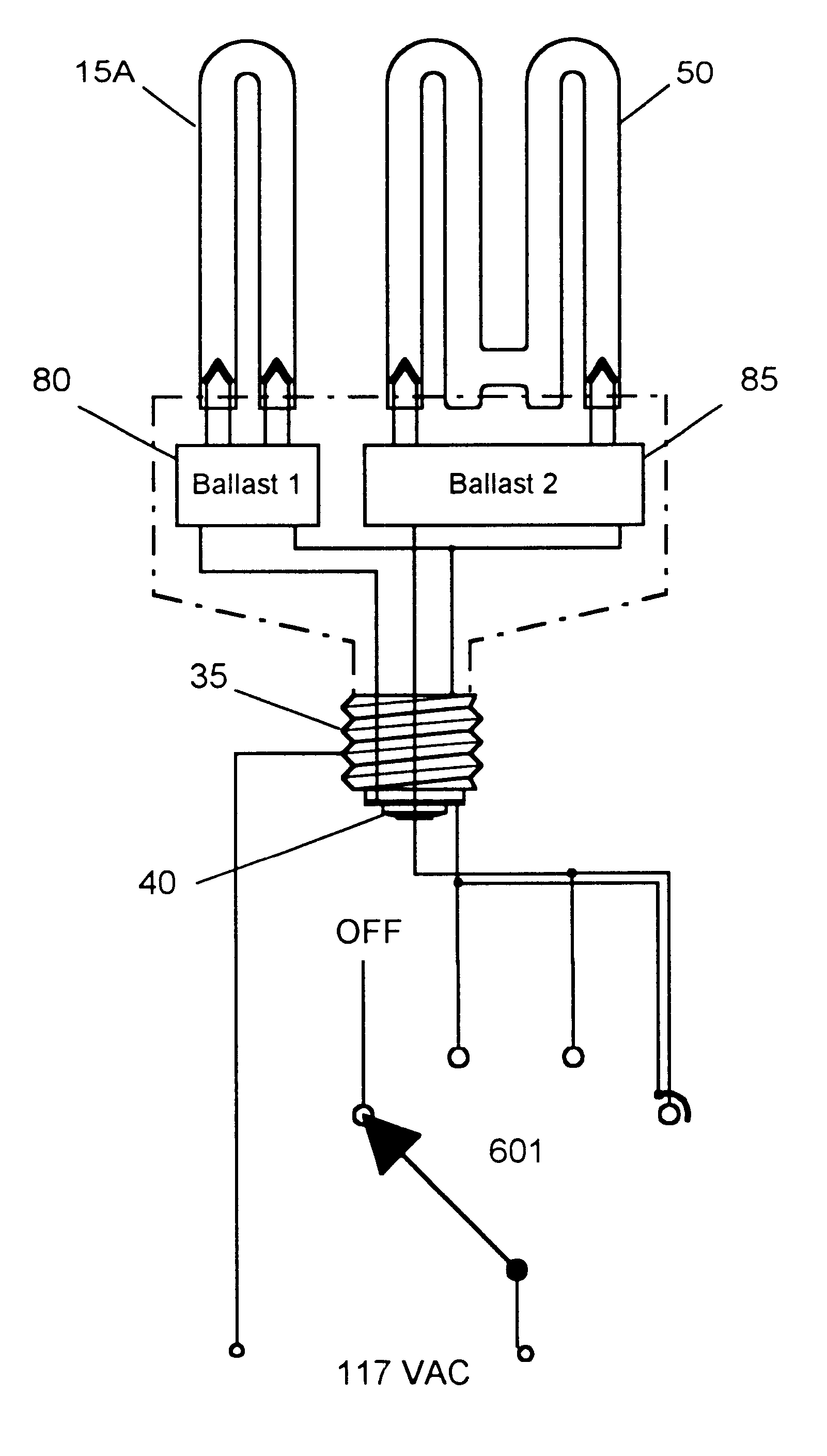
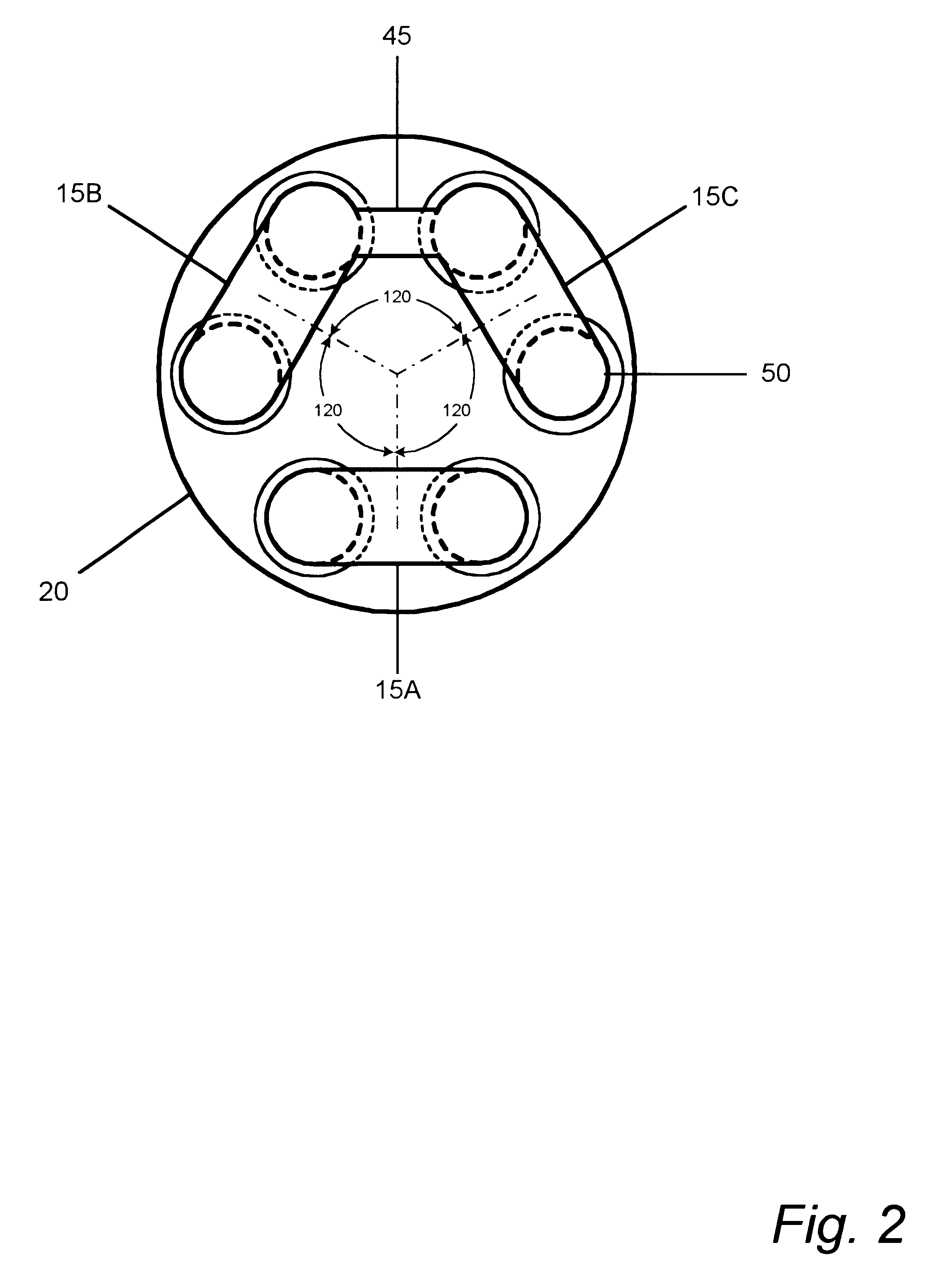
FIG. 1 is a side elevational view illustrating the dual element 3-way fluorescent lamp 10 comprised of three U-shaped lamp members 15A, 15B and 15C, permanently secured into the upper ballast housing 20. At the inward, upper edge of the lower ballast housing 25 is a circumferential ring that engages a retaining groove in the lower portion of the upper ballast housing 20 (not shown), which locks the two assemblies into a one-piece ensemble. Ventilation louvers 30 provide an adequate flow of air to cool the major heat generating devices contained within the ballast assembly. At the base of the lower ballast housing 25 is a standard medium base screw-in plug 35 that is adapted for insertion into a standard medium base screw-in lamp socket. At the bottom of the medium base screw-in plug 35 are a set of contacts having a 3...


PUM


Abstract

The present invention relates to a compact 3-way fluorescent lamp that is designed to serve as a replacement for a 3-way incandescent bulb. This novel compact 3-way fluorescent lamp uses only two fluorescent tubes, where one tube has twice the wattage rating of the smaller rated tube. The lower wattage unit is a single U-shaped tube and the higher wattage unit is comprised of a pair of U-shaped tubes, having a cross connection at the base of the tubes, giving a continuous gas discharge path through a first U-shaped tube, a cross connecting element, and a second U-shaped tube. Therefore, this lamp gives the appearance of a triple biaxial fluorescent lamp having three U-shaped units, spaced 120 degrees apart, and mounted to the top surface of a ballast housing cover. Two electronic ballasts ignite and operate the two lamp units-a low wattage ballast operates the low wattage unit, the medium wattage ballast operates the dual U-shaped medium wattage unit, and when both units are operational, the highest wattage level is attained. Each of the ballast circuits is optimized to give an enhanced high voltage ignition, thereby eliminating the need for an auxiliary ignition electrode. A pi-section EMI filter suppresses the electromagnetic interference that emanates from the MOSFETs as a result of their switching. Fire hazard protection is given by an internal fusible link.

Description

The present invention relates to electric discharge lamps having an ionizable gas discharge path with a luminescent material coating the walls of the discharge path, and more particularly, to a plurality of fluorescent electric discharge lamp elements supported on a base containing an integral self-contained electronic ballasting means, comprising a replaceable 3-way compact fluorescent lamp.Because of the demand for increased energy conservation due to the increased replacement and operating costs, researchers and innovators have been attempting to develop compact electric discharge lamps, such a fluorescent lamps, as screw-in replacements for the standard incandescent bulb. Up to now, these attempts have been hampered by lagging technologies that made large bulky inefficient assemblies that were expensive to manufacture and quite cumbersome at best.Electromagnetic ballasts, ones which were the predecessors to the electronic ballasts, had the disadvantage of being heavy because of ...

Claims


Application Information

Patent Timeline
Patent Type & Authority Patents(United States)
IPC IPC(8): H01J61/56H01J61/02H01J61/32H05B41/282H05B41/285H05B41/28
CPCH01J61/327H01J61/56H05B41/282H05B41/285Y02B20/183Y02B20/19Y02B20/00
Inventor YAN, ELLIS
Owner TECHNICAL CONSUMER PROD INC AN OHIO CORP
Why Eureka
Try Eureka