Optical system

Inactive Publication Date: 2002-10-01
MINOLTA CO LTD
View PDF11 Cites 44 Cited by
  • Summary
  • Abstract
  • Description
  • Claims
  • Application Information

AI Technical Summary

Benefits of technology

A purpose of this invention is to provide an optical system suitable for optical measuring apparatus for guiding rays emitted from an object to be measured a

Problems solved by technology

Such the problem is commonly exists in the optical systems used for measuring light sources having light distribution in w

Method used


Image

  • Optical system
  • Optical system
  • Optical system

Examples


first embodiment

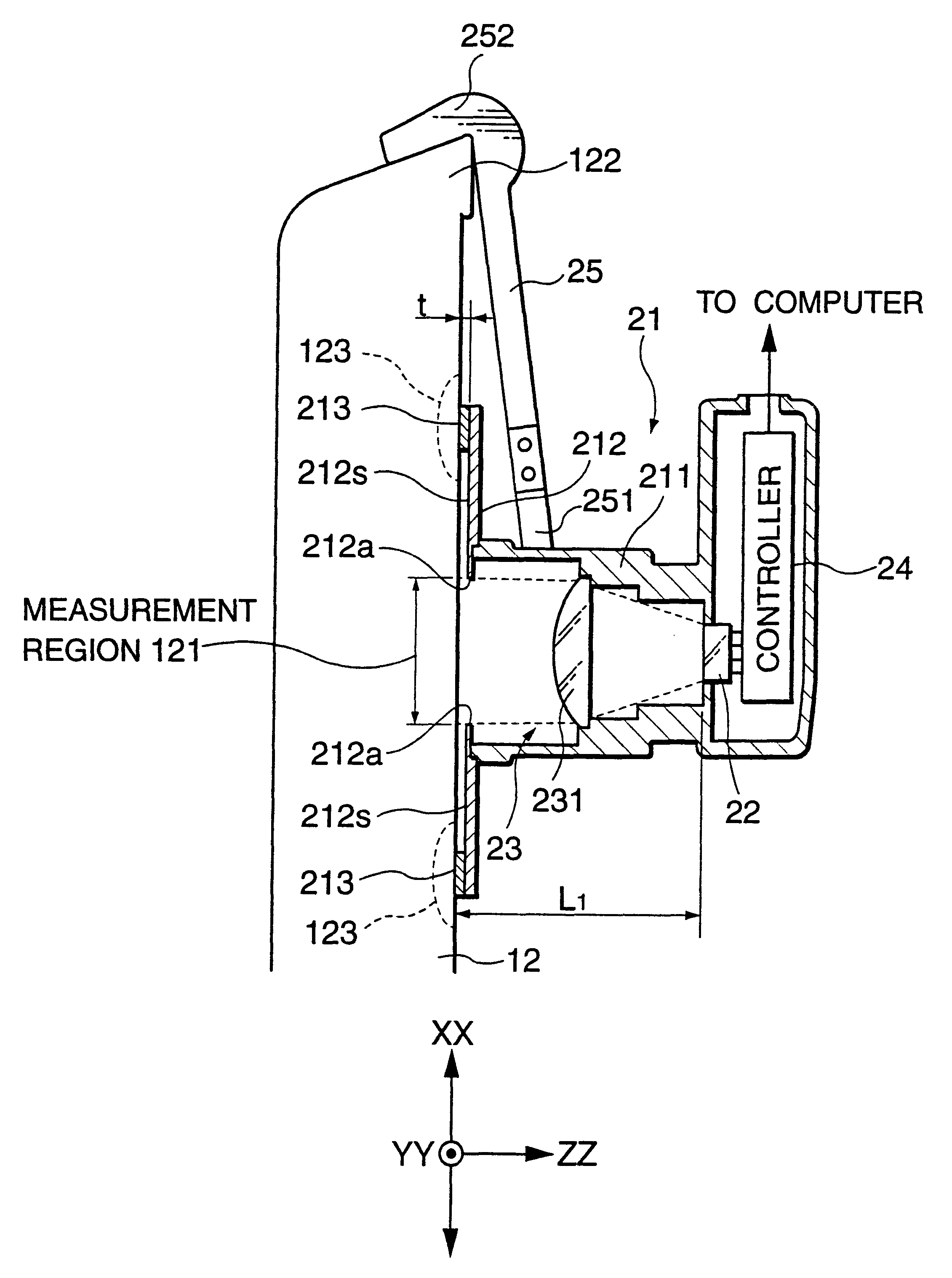
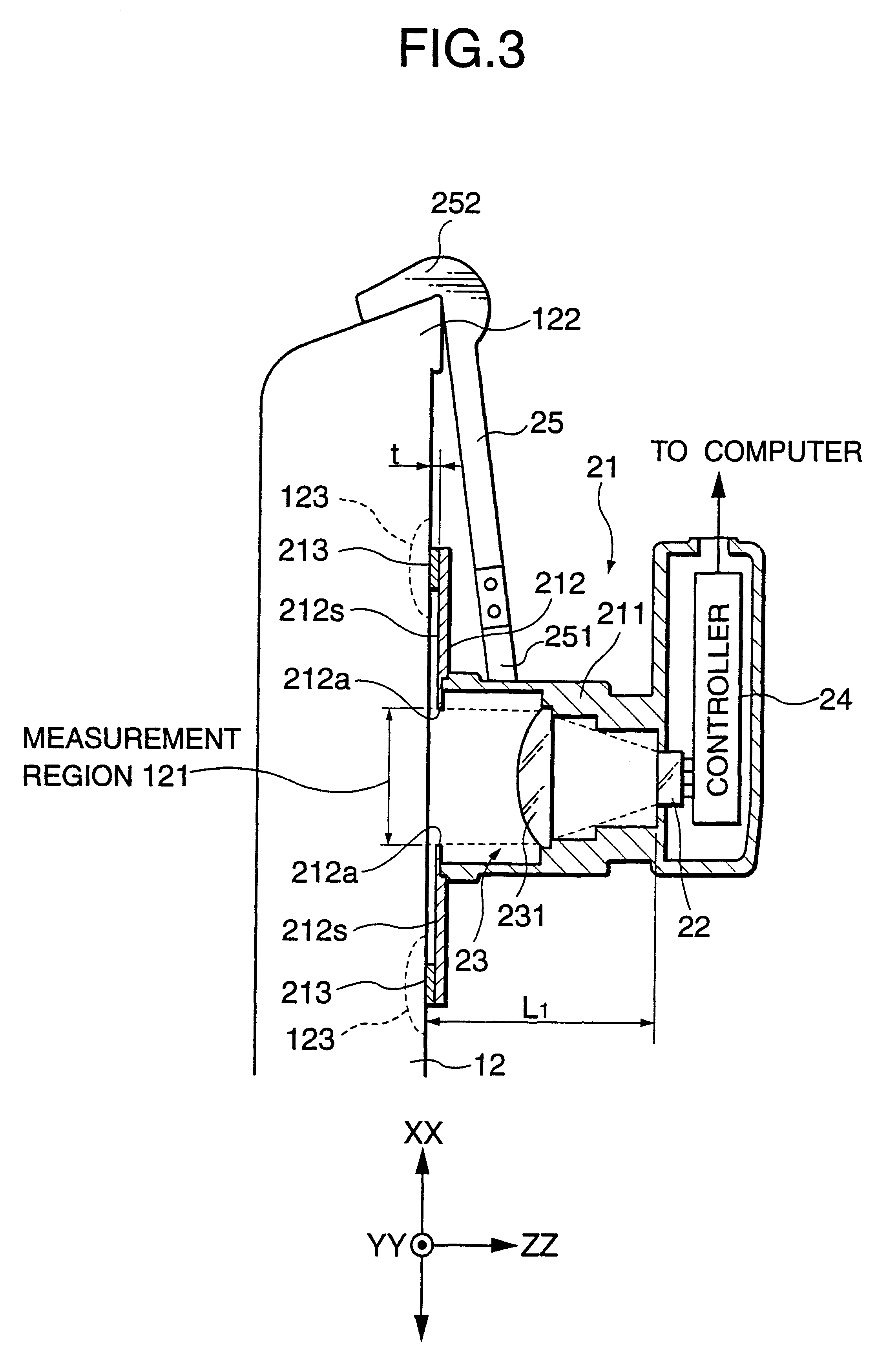
an optical system in accordance with this invention is described.

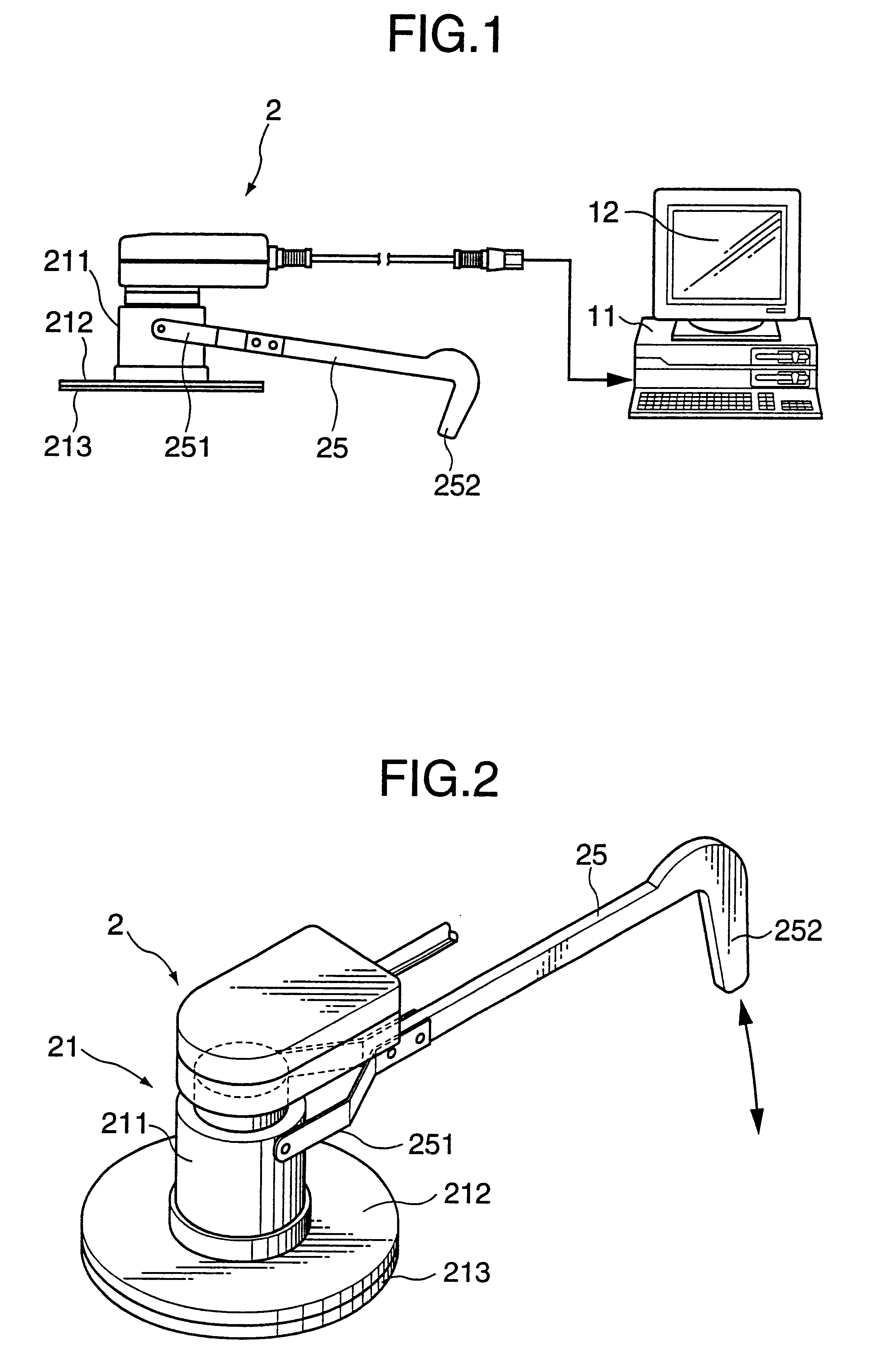
A calibration system of an LCD panel using an optical measuring apparatus with an optical system in accordance with the present invention is shown in FIG. 1. In the calibration system, an LCD panel 12 is electrically connected to a (personal) computer 11. Chromaticity, that is, tristimulus values of the LCD panel 12 is measured by an optical measuring apparatus 2, and result of measurement is inputted to the computer 11 through an interface such as RS232C and USB (Universal Serial Bus). The result of measurement is processed by a compensation program previously installed in the computer 11 for adjusting white balance of the LCD panel 12. As mentioned above, the light distribution of the LCD panel in the market generally varies from the symmetry in the vertical direction XX, but it is substantially symmetrical in the horizontal direction YY. Thus, it is assumed that the light distribution characteristics in the vertical...

second embodiment

the optical system 23 is shown in FIG. 10. In the second embodiment, any lens is used in the optical system 23. The distance between the opening 212a of the flange 212 and the photosensing plane RS of the photosensor 22 or the diameter of the opening 212a of the flange 212 is adjusted so that the ray emitted from, for example, the lower end 121b of the measurement region 121 with the maximum exit angle .alpha. reaches to the end of the photosensing plane RS of the photosensor 22.

third embodiment

the optical system 23 is shown in FIGS. 11 and 12. In the third embodiment shown in FIG. 11, a lens 232 having a focal length "f" is provided in a manner so that a principal point PP of the lens 232 in the object side is positioned at a position distant by a distance "f" from the measurement region 121, and the photosensing plane RS of the photosensor 22 is positioned at a position distant by a distance "f" from a principal point of the lens 232 in the image side. This configuration is generally called telecentric optical system in which the photosensor 22 serves as an aperture stop of the optical system 23.

As shown in FIG. 12, only the rays emitted from the measurement region 121 and having the exit angle equal to or larger than a predetermined angle .beta. and equal to or smaller than the maximum exit angle .alpha. reach to the photosensitive portion 221 to 224 of the photosensor 22. The exit angles .alpha. and .beta. depend on the focal length "f" of the lens 232 and the configur...


PUM


Abstract

An optical system used in an optical measuring apparatus for measuring optical characteristics of, for example, a liquid crystal display panel (LCD panel) guides rays emitted from the LCD panel and having exit angles equal to or smaller than a predetermined maximum exit angle alpha. A lens of the optical system satisfies the following two equations.Hereupon, the symbol "f" designates a focal length of the lens; the symbol "h" designates the maximum height of the photosensitive plane of the photosensor from an optical axis of the lens on the photosensing plane; the symbol "L" designates a distance from a principal point of the lens in the image side to the photosensing plane; and the symbol "H" designates the maximum height of the object from the optical axis of the lens.

Description

This application is based on patent application Hei.11-23095 filed in Japan, the contents of which are hereby incorporated by references.1. Field of the InventionThis invention relates to an optical system used in an optical measuring apparatus for guiding rays emitted from an object to be measured and having exit angles equal to or smaller than a predetermined angle to a photosensing plane of a photosensor in the optical measuring apparatus.2. Description of the Related ArtAn optical measuring apparatus has conventionally been used in a manufacturing line of a liquid crystal display panel (hereinafter abbreviated as LCD panel) for measuring optical characteristics such as chromaticity and luminance. Adjustment of white balance, quality control and shipping inspection of the LCD panel are executed by using the result of the measurement of the optical characteristics.A conventional optical measuring apparatus comprises a photosensor for receiving rays emitted from a region of an LCD ...

Claims


Application Information

Patent Timeline
IPC IPC(8): G02B6/02G02B6/04G01J1/00G01J1/06G01J3/46G01M11/00
CPCG01M11/00G02B6/02G02B6/04
Inventor TSURUTANI, KATSUTOSHI
Owner MINOLTA CO LTD
Why Eureka
Try Eureka