Method of disinfecting a deionized water producing apparatus and method of producing deionized water

Inactive Publication Date: 2002-10-08
KURITA WATER INDUSTRIES LTD
View PDF5 Cites 53 Cited by
  • Summary
  • Abstract
  • Description
  • Claims
  • Application Information

AI Technical Summary

Benefits of technology

It is an object of the present invention to solve aforementioned conventional problems and to provide a method of disinfecting deionized water producing appa

Problems solved by technology

However, the efficiency of disinfection is insufficient.
The number of bacteria inc

Method used


Image

  • Method of disinfecting a deionized water producing apparatus and method of producing deionized water
  • Method of disinfecting a deionized water producing apparatus and method of producing deionized water
  • Method of disinfecting a deionized water producing apparatus and method of producing deionized water

Examples


example 1

City water of Atsugi, Kanagawa Japan was treated at a rate of 0.5 m.sup.3 / hr by the apparatus of FIG. 3.

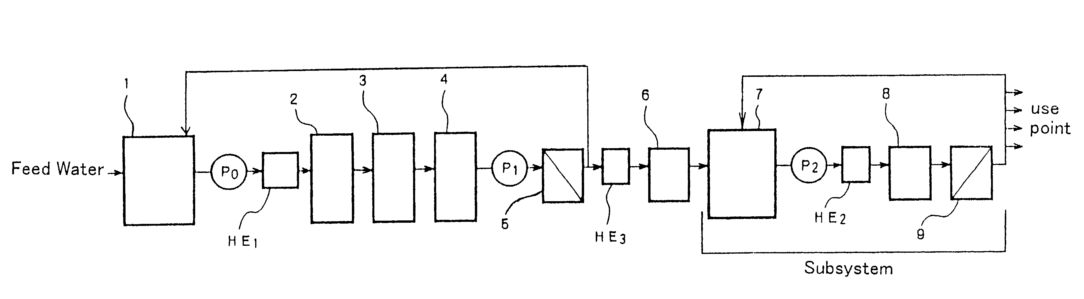
In this apparatus, feed water of the above city water was flown through the heat exchanger 21, treated by the microfiltration (MF) apparatus 22 and the activated carbon (AC) tower 23, and fed from the tank 24 to the RO apparatus 25 via the pump P. Permeated water from the RO apparatus 25 was heat-exchanged by the heat exchanger 26 and treated by the electrodeionization apparatus 27. The particulars of the apparatuses are as follows:

MF apparatus 22: "Kuriequrun" of Kurita Water Industries Ltd.

AC tower 23: "Kurare Coal KW" of Kurare Co., Ltd.

RO apparatus 27: "SG 4040CZH of Desari Co,. Ltd. having a diameter of 4 inches Electrodeionization apparatus 27: "CDI P--10 of U.S. Filter / Ionpure, Inc. having 10 cells; mixture of anion exchanger and cation exchanger being filled in both diluting compartment and concentrating compartment:

The deionized water apparatus 27 is of the type where fe...


PUM

PropertyMeasurementUnit
Temperatureaaaaaaaaaa
Angleaaaaaaaaaa

Abstract

A deionized water producing apparatus includes a pretreatment apparatus having a reverse osmosis apparatus, and an electrodeionization apparatus having a diluting compartment filled with an ion exchanger. In order to disinfect the deionized water producing apparatus, hot water of higher than 80° C. is flown through the pretreatment apparatus, and hot water of higher than 60° C. is flown through the electrodeionization apparatus. Hot water flowing thorough the electrodeionization apparatus is gradually heated at a rate of 0.1-10° C./min.

Description

The present invention relates to a method of disinfecting deionized water producing apparatus and a method of producing deionized water with using the electrodejonization apparatus disinfected by disinfecting method.A conventional system for producing purified water which is employed in fields of the pharmaceutical manufacturing industry, the semiconductor manufacturing industry and the like is shown FIGS. 2a and 2b.FIG. 2a is a system diagram illustrating a system for producing deionized water employed in the field of the pharmaceutical manufacturing industry, in which raw water is treated with an activated carbon (AC) column or tower 2, a safety filter 3 and a membrane degassing apparatus 4 by way of a tank 1, a pump P0 and a heat exchanger HE1, and then the water is pressured by a pump P1 and treated with a reverse osmosis membrane (RO) apparatus 5 and an electrodeionization apparatus 6. After that, the water is treated with a subsystem comprising an ultraviolet (UV) disinfecting...

Claims


Application Information

Patent Timeline
IPC IPC(8): B01J47/08B01J47/00B01D61/48B01D61/42B01D65/02B01D61/58B01D61/52B01D65/00C02F9/00C02F1/44C02F1/469C02F1/02C02F1/20C02F1/28C02F1/32C02F9/02
CPCB01D65/022B01J47/08C02F9/00B01D61/48B01D61/52B01D61/58C02F1/02C02F1/20C02F1/283C02F1/32C02F1/441C02F1/444C02F1/4693C02F2103/04C02F2303/04C02F1/469B01D61/025B01D61/145B01D61/147B01D2321/08
Inventor HIRAYAMA, JUNYASATO, SHIGEAKI
Owner KURITA WATER INDUSTRIES LTD
Why Eureka
Try Eureka