Magnetic circuit

a technology of magnetic circuits and circuits, applied in the direction of magnets, magnetic bodies, mechanical apparatus, etc., can solve the problems of many internal parts, complex designs, and difficult to meet the requirements of economical manufacturing and assembly procedures, and achieve the effect of maximizing torque and heat dissipation

Inactive Publication Date: 2002-10-15
DREW CHESTER
View PDF13 Cites 34 Cited by
  • Summary
  • Abstract
  • Description
  • Claims
  • Application Information

AI Technical Summary

Benefits of technology

is to maximize torque and heat dissipation by placing the torque produc

Problems solved by technology

While numerous configurations have been created, many have involved complex designs which do not lend themselves to economical manufacturing and assembly procedures.
This requires expensive machining.
The many internal parts increase assembly time.
Also the more parts that are used, the chances for assembly errors such as misaligning components are increased.
U.S. Pat. No. 4,681,197 does increase torque output per size but requires a more complex rotor design.
This increases machining complexity and difficulty in assembly.
Since this necessitates a relatively small cross sectional area, torque is limited.
So even if the torque level can be increased, heat dissipation is limited thereby limiting the force and duty cycle of the device.
Other configurations are not in

Method used


Image

  • Magnetic circuit
  • Magnetic circuit
  • Magnetic circuit

Examples


Embodiment Construction

. 1-2

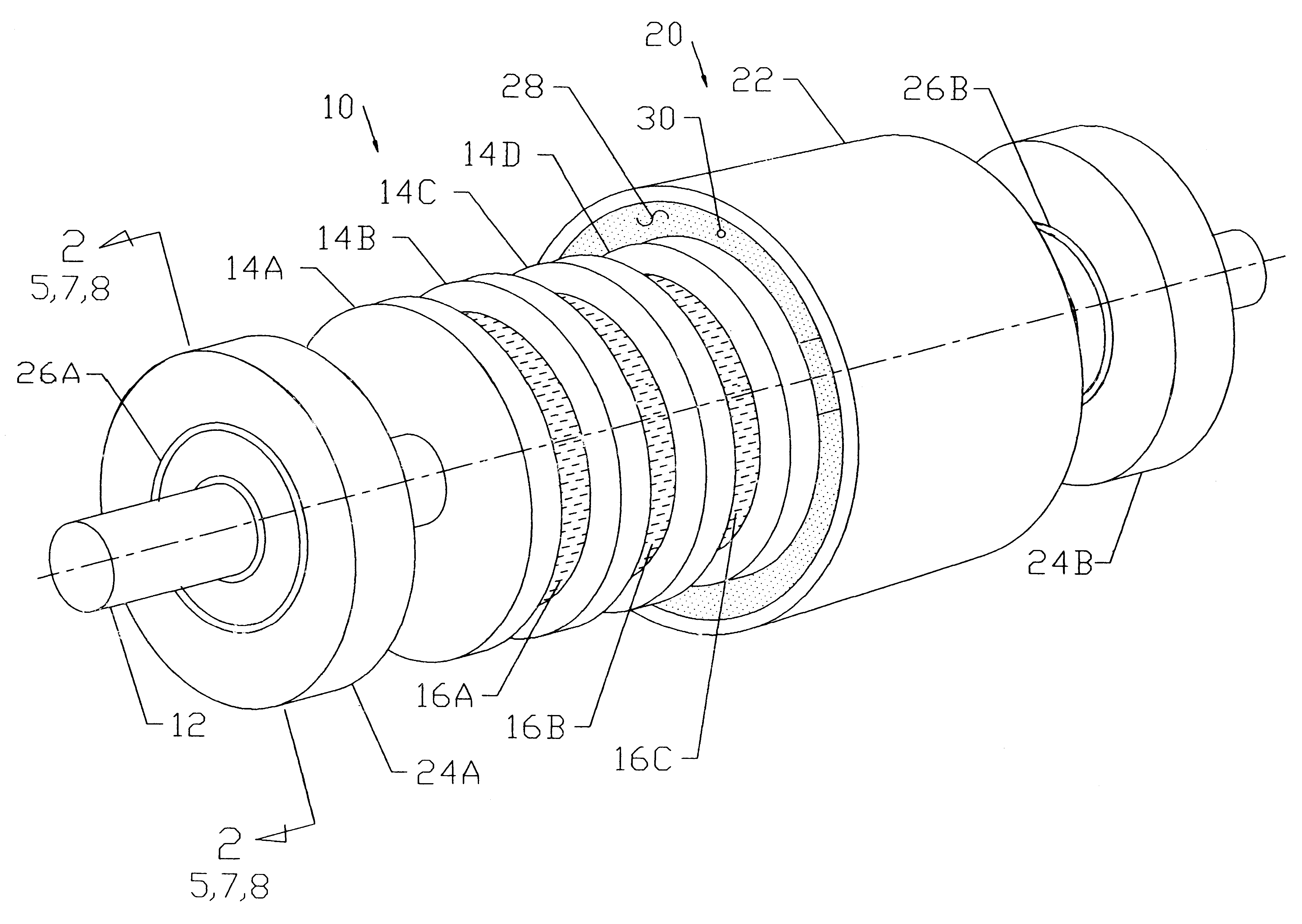
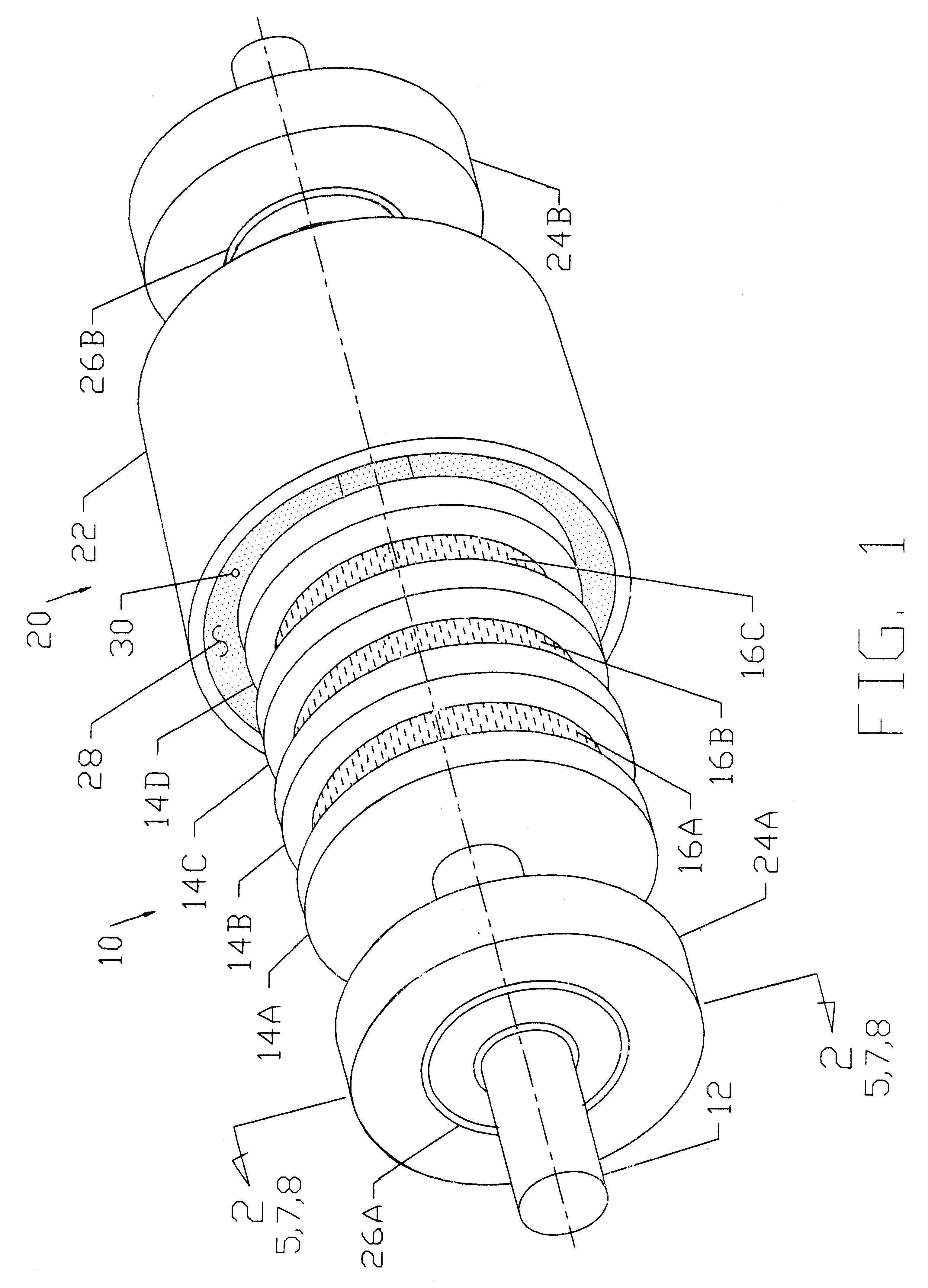
A perspective view of a typical embodiment of the clutch is shown in FIG. 1. The device comprises a shaft assembly 10. The shaft assembly consists of a rotary shaft 12 with a series of round washers 14A, 14B, 14C, and 14D pressed onto the shaft. These washers are made of low carbon (eg. AISI 1018) steel and are magnetically conductive. The thickness is approximately 1 / 15 the washer's outer diameter. A ring magnet 16A, 16B, and 16C is placed between each washer. The diameter is slightly less than the washer's diameter. The magnet's thickness is approximately 1 / 15 its diameter. "High-energy" magnets which have a typical energy product of 27 mega-gauss oersteds are used. The material composition is neodymium, iron, and boron. The magnets 16 are bonded to the washers 14 with a suitable adhesive. The magnets 16 are magnetized through the thickness with each face being of opposite magnetic polarity. They are bonded to the washers 14 with like poles facing each other.

FIG. 1 also shows...


PUM


Abstract

A magnetic circuit design comprises a shaft assembly (10) consisting of a moveable shaft (12) and a series of washers (14) and magnets (16) mounted axially along the length of the shaft (12). The magnets (16) are positioned between the washers (14) with like magnetic poles facing each other. Additional washers (14) and magnets (16) may be stacked axially along the shaft (12). A cylinder assembly (20) consists of a cylinder (22) with housings (24A) and (24B) in each end. The shaft assembly (10) is positioned concentrically inside cylinder assembly (20) and is relatively rotatable to cylinder assembly (20) by means of bearings (26A) and (26B) inserted into housings (24A) and (24B). A fine magnetic powder (30) fills the air gap (28) created between the shaft (10) and the cylinder (20) assemblies.

Description

1) Field of the InventionThis invention relates to magnetic circuits which use permanent magnets to create a magnetic field, specifically the invention relates to a magnetic circuit design used in magnetic particle clutches and brakes which are used to create a resisting force for linear or rotary motion.2) Background of the Prior ArtMagnetic particle devices have been used where long life and stable, consistent torque have been important. One example is tensioning of wire when winding electric coils. In this case, long brake life is important since the brake is slipping continuously as it applies tension to the moving wire. Furthermore, the tension must be stable and repeatable to ensure the coil is wound with consistent tension but not with tension so high that the wire stretches or breaks.While numerous configurations have been created, many have involved complex designs which do not lend themselves to economical manufacturing and assembly procedures. For example, U.S. Pat. No. 3...

Claims


Application Information

Patent Timeline
IPC IPC(8): F16D43/00F16D43/20
CPCF16D43/20
Inventor DREW, CHESTER
Owner DREW CHESTER
Why Eureka
Try Eureka