Pulsed system and method for fiber optic sensor

a fiber optic sensor and fiber optic sensor technology, applied in the field of fiber optic sensor systems, can solve the problems of large phase drift, limited response of mach-zehnder interferometer, and increased interferometer path differences, so as to reduce the noise associated with the effect of detecting the phase nois

Inactive Publication Date: 2002-10-15
NAVY US SEC THE NAVY THE
View PDF5 Cites 77 Cited by
  • Summary
  • Abstract
  • Description
  • Claims
  • Application Information

AI Technical Summary

Benefits of technology

It is another object of the present invention to reduce the noise associated with the pulses by chirping the dual pulses.

Problems solved by technology

Phase noise of a coherent light source, as detected by the photoreceiver, increases with increased interferometer path differences.
The response of a Mach-Zehnder interferometer may be limited by phase noise if the path differences for the reference and the signal beams are large.
As well, large phase drifts may be produced in such systems due to temperature effects on the interferometer.
Amplitude noise may also be produced by self-interference of the lightwave due to scattering or reflecting within the fiber optic paths.
Previous methods for generating light pulses for general usage are not always suitable for fiber optic sensor systems.
For purposes of fiber optic sensor system, this method is considered to be difficult to control and produces noisy signals that are not highly repeatable.
The prior art does not disclose a pulsed fiber optic sensor system wherein pulses may pass through several fiber optic sensor arrays.

Method used


Image

  • Pulsed system and method for fiber optic sensor
  • Pulsed system and method for fiber optic sensor
  • Pulsed system and method for fiber optic sensor

Examples


Embodiment Construction

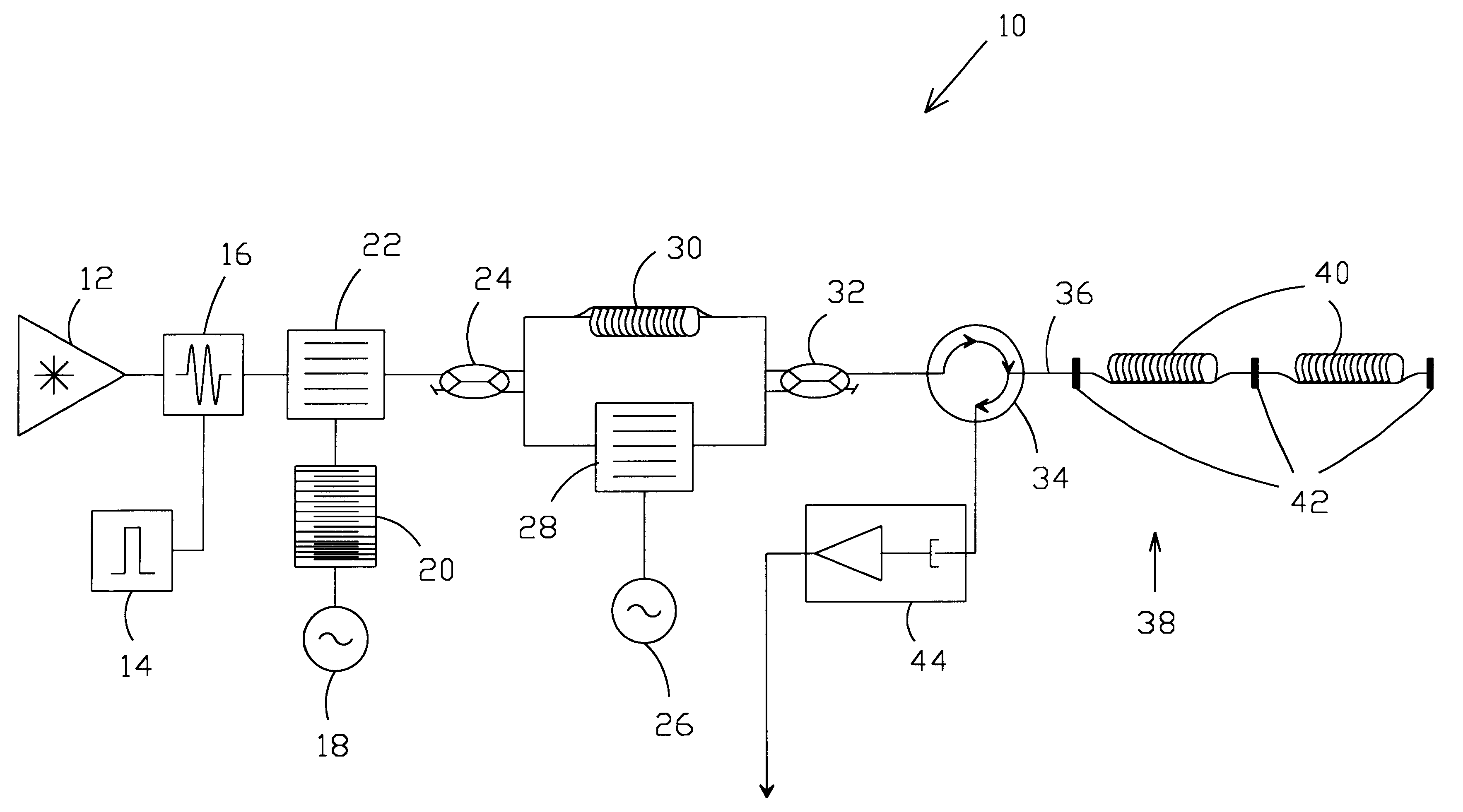
Referring now to the drawings and, more particularly, to FIG. 1 there is shown a fiber optic sensor system 10 in accord with the present invention. While the present invention is especially useful with one or more arrays of fiber optic acoustic sensors, it could also be used with or in combination with other types of fiber optic sensors.

In one presently preferred embodiment of the present invention, a single light pulse is initially created utilizing light from coherent light source 12. For this purpose, a gate signal is produced by gating circuit 14 and applied to amplitude modulator 16 to switch light on and then off to produce the single light pulse. A pulsed frequency signal or impulse is produced by pulsed frequency signal generator or impulse generator 18 for application into a surface acoustic wave (SAW) device 20 to create a chirp signal in accord with the present invention that provides a novel approach for generating a chirp signal. As discussed herein, a pulse is of a sho...


PUM


Abstract

A system and method is disclosed for generating, propagating, and detecting light pulses for use with a fiber optic transducer array. The system preferably uses two pulses to provide fixed and relatively short interferometer path differences to thereby reduce coherent light noise. The system preferably uses a surface acoustic wave device for chirping the light pulses to thereby spread noise over a wider bandwidth so as to suppress noise. A coherent light source is preferably amplitude modulated to produce an initial pulse. In one embodiment, that initial pulse is chirped and split into two pulses. One of the two pulses is delayed while the other is frequency shifted. The two pulses are combined onto a single fiber optic path and applied to the fiber optic transducer array. After being acted on by the fiber optic transducer array, the two pulses are photodetected and processed to obtain the information about the physical phenomena to be detected.

Description

(1) Field of the InventionThe present invention relates generally to fiber optic sensor systems and, more specifically, to apparatus and method for fiber optic sensing including generating, propagating, and detecting highly repeatable pulses through a fiber optic sensor system.(2) Description of the Prior ArtPrior art fiber optic sensor systems, such as fiber optic acoustic sensor systems, typically incorporate either Michelson or Mach-Zehnder type interferometers. These interferometers have high sensitivity and high dynamic range. In using these interferometers, a continuous light wave is split into two paths. The first path is used as a reference giving rise to a reference beam, while the second path is used as the sensor path which provides the signal beam. The acoustic field modulates the lightwave in the second path, usually by means of a fiber optic transducer. The two beams (reference beam and the signal beam) are recombined and the resulting interference is detected at a pho...

Claims


Application Information

Patent Timeline
Patent Type & Authority Patents(United States)
IPC IPC(8): G01D5/353G01D5/26G01H9/00
CPCG01D5/35303G01H9/004
Inventor GO, VINSON L.BAKER, DANIEL L.
Owner NAVY US SEC THE NAVY THE
Why Eureka
Try Eureka