Hot-water supply system with heat pump cycle

a technology of hot water supply system and heat pump cycle, which is applied in the direction of heating types, instruments, domestic cooling apparatus, etc., can solve the problem of difficult control of the expansion valve due to the temperature differen

Inactive Publication Date: 2002-10-22
DENSO CORP +2
View PDF8 Cites 64 Cited by
  • Summary
  • Abstract
  • Description
  • Claims
  • Application Information

AI Technical Summary

Benefits of technology

It is a second object of the present invention to provide a hot-water supply system with a heat pump cycle, capable of resolving insufficient ability and securing a target hot-water supply temperature during a boiling-up operation without adding any new functional components, and improving stability and reliability of a hot-water control in low cost.
According to a further another aspect of the present invention, when temperature of the fluid at the inlet side of the fluid passage is lower than a control change temperature, the control unit controls the opening degree of the expansion valve so that a temperature difference between the refrigerant temperature at the outlet side of the refrigerant passage and the fluid temperature at the inlet side of the fluid passage is within a predetermined range. On the other hand, when the temperature of the fluid at the inlet side of the fluid passage is equal to or higher than the control change temperature, the control unit controls the opening degree of the expansion valve to be decreased when a refrigerant temperature discharged from an outlet of the compressor is equal to or lower than a first refrigerant set temperature, and controls the opening degree of the expansion valve to be increased when the refrigerant temperature discharged from the outlet of the compressor is equal to or higher than a second refrigerant set temperature set higher than the first refrigerant set temperature. In addition, the control unit controls the capacity of the pump to be increased when the temperature of the fluid at the outlet side of the fluid passage is equal to or higher than a first fluid set temperature, and controls the capacity of the pump to be decreased when the temperature of the fluid at the outlet side of the fluid passage is equal to or lower than a second fluid set temperature lower than the first fluid set temperature. Accordingly, the hot-water supply system can accurately perform a control immediately before the boiling-up.

Problems solved by technology

Particularly, when temperature of hot-water within the hot-water storage tank has lowered by stopped operation for many hours and thereafter the hot-water is boiled up again, or when the temperature of hot-water within the hot-water circuit including the hot-water storage tank is ununiform, there arises a problem.
In addition, because the temperature of hot water in the hot water circuit increases with an elapse time of operation of the hot-water supply system, the temperature difference between the refrigerant temperature on the outlet side of the refrigerant flow passage and the hot-water temperature on the inlet side of the hot-water flow passage becomes smaller in a final stage of boiling up of hot water, and the control of the expansion valve due to the temperature difference becomes difficult.

Method used


Image

  • Hot-water supply system with heat pump cycle
  • Hot-water supply system with heat pump cycle
  • Hot-water supply system with heat pump cycle

Examples


first embodiment

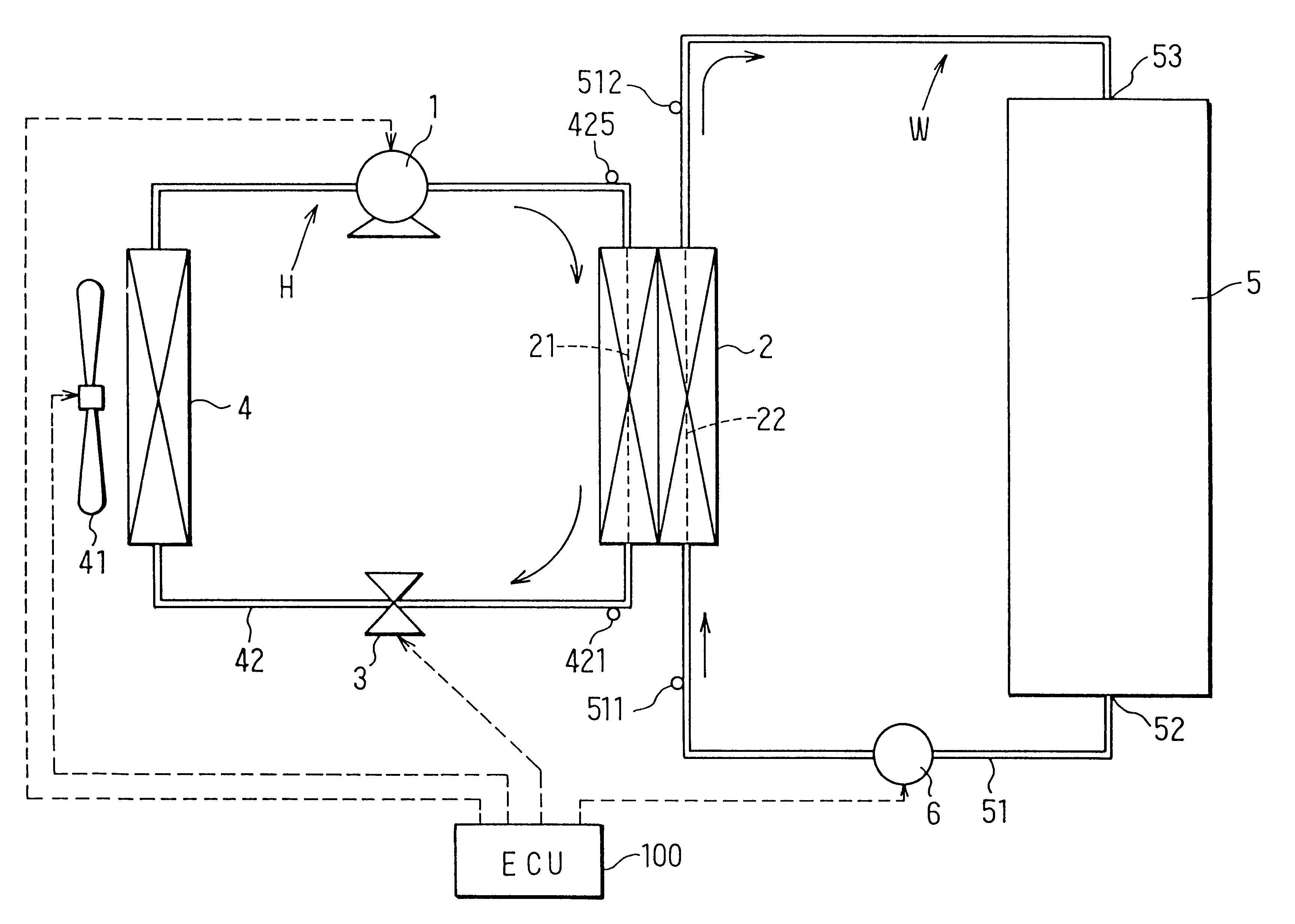
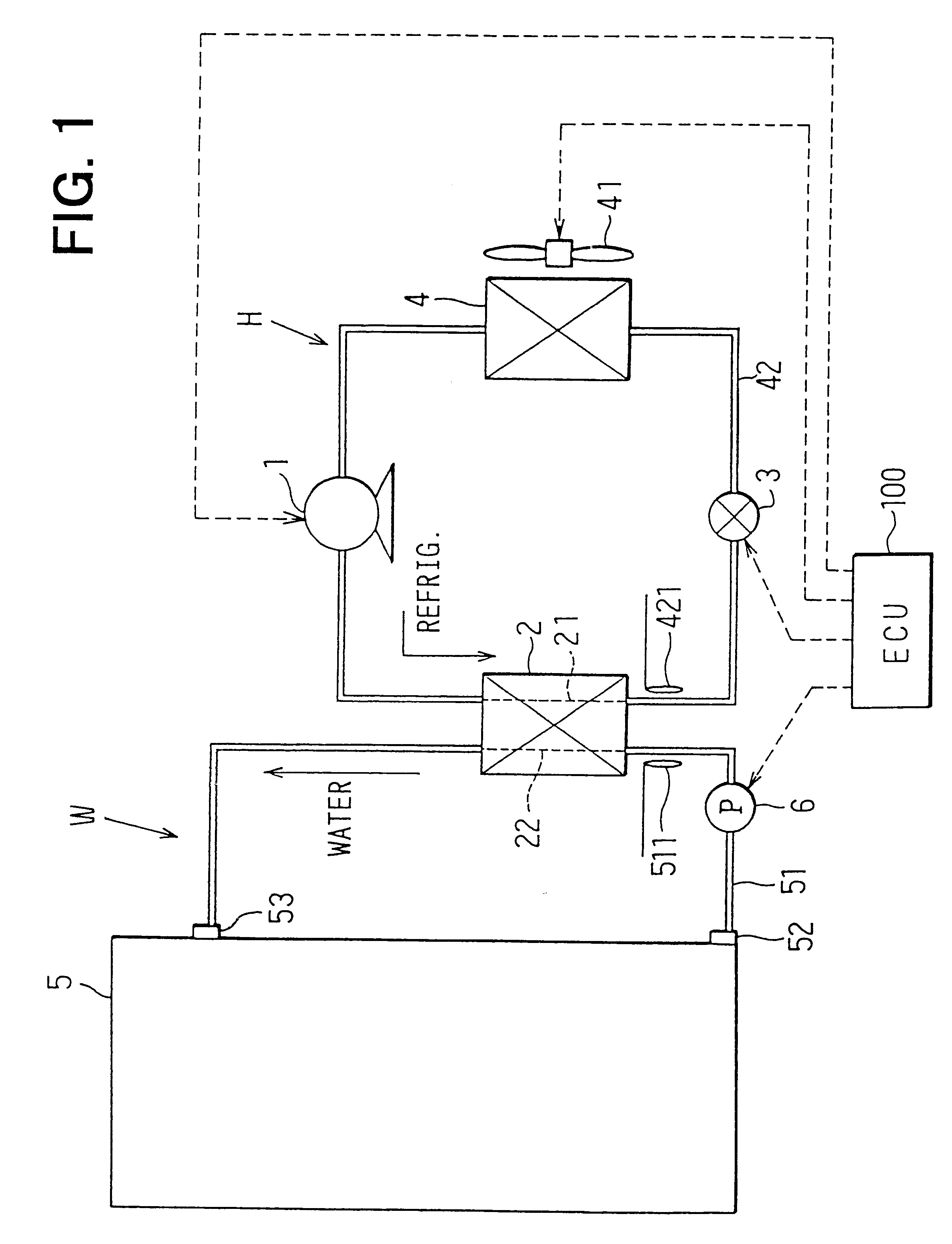
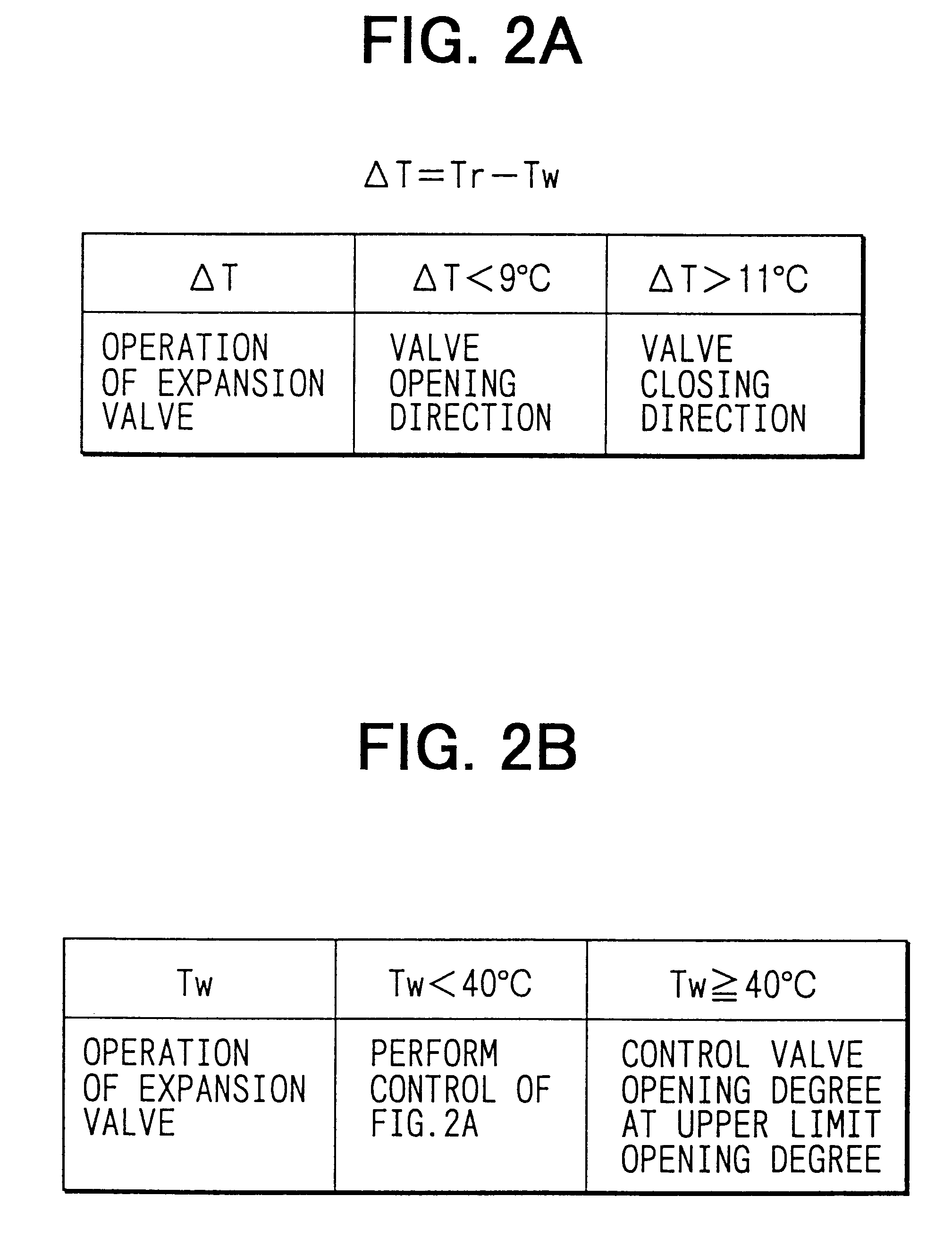
That is, the temperature difference .DELTA.T is a difference between the refrigerant outlet temperature Tr detected by the refrigerant temperature sensor 421 and the water temperature Tw detected by the water temperature sensor 511 (.DELTA.T=Tr-Tw). In the first embodiment, when the water temperature Tw is lower than a predetermined temperature (e.g., 40.degree. C.), the valve opening degree of the expansion valve 3 is controlled in accordance with whether or not this temperature difference .DELTA.T is within a target temperature difference range (for example, 9.degree. C.-11.degree. C.). Specifically, when the temperature difference .DELTA.T is smaller than 9.degree. C., the expansion valve 3 is operated in a direction that opens the valve. On the other hand, when the temperature difference is larger than 11.degree. C., the expansion valve 3 is operated in a direction that closes the valve. The target temperature difference range can be made constant, and may be set to be changed o...

second embodiment

In the second embodiment, after the water temperature Tw' becomes the target water temperature To, the rotation speed of the compressor 1 can be controlled in accordance with the reference pattern in FIG. 5B. In this case, the coefficient of performance (COP) in the heat pump cycle H can be further improved.

In the second embodiment, the increasing ratio in the rotation speed of the compressor 1 is set in accordance with the temperature difference (To-Tw') between the target hot-water supply temperature To and the actual hot-water supply temperature Tw'. However, the opening degree of the expansion valve 3 may be F / B controlled in accordance with the temperature difference (To-Tw'). In this case, if the target hot-water supply temperature To>the actual hot-water supply temperature Tw', the expansion valve 3 is driven in the direction reducing the opening degree. On the other hand, when the target hot-water supply temperature To

third embodiment

Thus, in the third embodiment, when a temperature difference (Tr'-Tam) between a refrigerant temperature detected by the refrigerant inlet temperature sensor 422 and the outside air temperature Tam detected by the outside air temperature sensor 423 is equal to or higher than 0.degree. C. [i.e., (Tr'-Tam).gtoreq.0.degree. C.] as shown in FIG. 8, as the temperature difference (Tr'-Tam) increases, the increasing ratio in the rotation speed of the compressor 1 is increased by the control unit 100. Further, in order to prevent heat from being radiated from the refrigerant in the air heat exchanger 4, the operation of the outdoor fan 41 attached onto the air heat exchanger 4 is stopped when (Tr'-Tam).gtoreq.0.degree. C. Thereby, the cycle high pressure can be maintained in the heat pump cycle. Accordingly, it is possible to secure the hot-water supply ability, to maintain the hot-water supply temperature at the target hot-water supply temperature, and to prevent heat radiation loss in the...


PUM


Abstract

In a hot-water supply system with a heat pump cycle, a control unit controls operation of an expansion valve based on a temperature difference between a refrigerant temperature at an outlet side of a refrigerant passage in a water heat exchanger and a water temperature at an inlet side of a water passage in the water heat exchanger. When the expansion valve is controlled in a direction increasing a valve opening degree, the control unit sets an upper limit opening degree of the expansion valve, for obtaining a refrigerant pressure corresponding to a target hot-water temperature, and controls the expansion valve in an opening degree range smaller than the upper limit opening degree.

Description

This application is related to Japanese Patent Applications No. 2000-167510 filed on Jun. 5, 2000, No. 2000-344206 filed on Nov. 10, 2000, and No. 2001-116959 filed on Apr. 16, 2001, the contents of which are hereby incorporated by reference.1. Field of the InventionThe present invention relates to a heat-pump type hot-water supply system, and more particularly, relates to technique for restraining a decrease of boiling-up ability resulting from an increase in a water temperature in a final stage of boiling-up and for reducing running cost by optimizing a boiling-up terminating condition.2. Description of Related ArtApplicants of the present application invented a hot-water supply system with a heat pump cycle which includes a refrigerant compressor, a refrigerant flow passage of a water heat exchanger, an expansion valve, an air heat exchanger provided with an outdoor fan, and a hot water circuit. In the hot water circuit, a hot-water storage tank for storing hot water for a hot-wa...

Claims


Application Information

Patent Timeline
Patent Type & Authority Patents(United States)
IPC IPC(8): F24D19/00F24D19/10F25B49/02F24H4/00F24H4/04F25B41/06F25B30/02F25B30/00G05D23/19F25B9/00F24H1/00F25B1/00
CPCF24D19/1054F24H4/04F25B30/02F25B41/062F25B49/027G05D23/1923F24F2011/0094F25B9/008F25B2309/061F25B2339/047F25B2600/0253F25B2600/17F25B2600/2513F25B2700/2106F25B2700/2116F25B2700/21161F25B2700/21174F25B2700/21175Y02B30/741F24F11/47Y02B30/70F25B41/34F24H15/175F24H15/232F24H15/38F24H15/258F24H15/156F24H15/385F24H15/215F24H15/231
Inventor KUROKI, JYOUJISAKAKIBARA, HISAYOSHIYOSHIMI, TOMOHISAKOBAYAKAWA, TOMOAKIKUSAKARI, KAZUTOSHISAIKAWA, MICHIYUKI
Owner DENSO CORP
Why Eureka
Try Eureka