Apparatus for pad printing a conductive picture on an irregular surface

a technology of irregular surfaces and pads, applied in the direction of pattern printing, conductive pattern formation, printing, etc., can solve the problems of strong restrictions on printing techniques, and achieve the effect of facilitating the cover of irregularities

Inactive Publication Date: 2002-10-29
BLACKBERRY LTD
View PDF8 Cites 8 Cited by
  • Summary
  • Abstract
  • Description
  • Claims
  • Application Information

AI Technical Summary

Benefits of technology

By printing partial pictures on the surface of the detail rather than printing the complete picture in one printing, it is easier to cover all irregularities on the surface of the detail.
Another advantage is that the printing means can have a specific design for each particular irregularity to be printed with a partial picture. This increases of course the surface accessibility of the detail.
Since the pad has a shape corresponding to the detail to be printed, e.g. a mobile phone casing, it is easier for the colour to cover all irregularities of the detail. Moreover, the printing of the detail can be carried out in fewer steps.
The method described above is a very simple and fast way of applying a circuit pattern on for example a PCB; fetching a circuit pattern from a cliche by means of a tampon pad and then printing the pattern on the PCB or a telephone casing. This method could readily be used in a very fast production line described below for manufacturing of phone casings or PCB's applied with this electrical circuit pattern. Wider electrical lines, as for example power lines or antenna pattern lines, are particularly suitable for this method. The method could for example be used for printing the antenna pattern on the flip of the phone casing.
In one embodiment of the invention, the printing means prints the conductive partial pictures on the surface of the detail from different application angles for better surface accessibility of the irregularities.
A preferable design of the cliche is suggested in the dependent claims, wherein the cliche at some areas of the surface have deep recesses to contain more colour. These areas correspond to irregular areas of the mobile phone casing needing more colour. Also a curved cliche is suggested in the dependent claims for facilitating for the tampon pad to absorb the colour.

Problems solved by technology

However, today's printing technique imposes strong restrictions when it comes to printing on somewhat more complicated surfaces.
If the skilled person wants to print e.g. a conductive layer using today's technique (spraying, vacuum metallization) on for example the inside of a mobile phone casing which has surfaces of the type described above, this will be very expensive, time consuming and still the result will be unsatisfactory since the printing colour (picture) will not cover the entire irregularities.
However, these applications are not explicitly related to the printing on irregularities of a detail, e.g. a mobile phone casing.

Method used


Image

  • Apparatus for pad printing a conductive picture on an irregular surface
  • Apparatus for pad printing a conductive picture on an irregular surface
  • Apparatus for pad printing a conductive picture on an irregular surface

Examples


Embodiment Construction

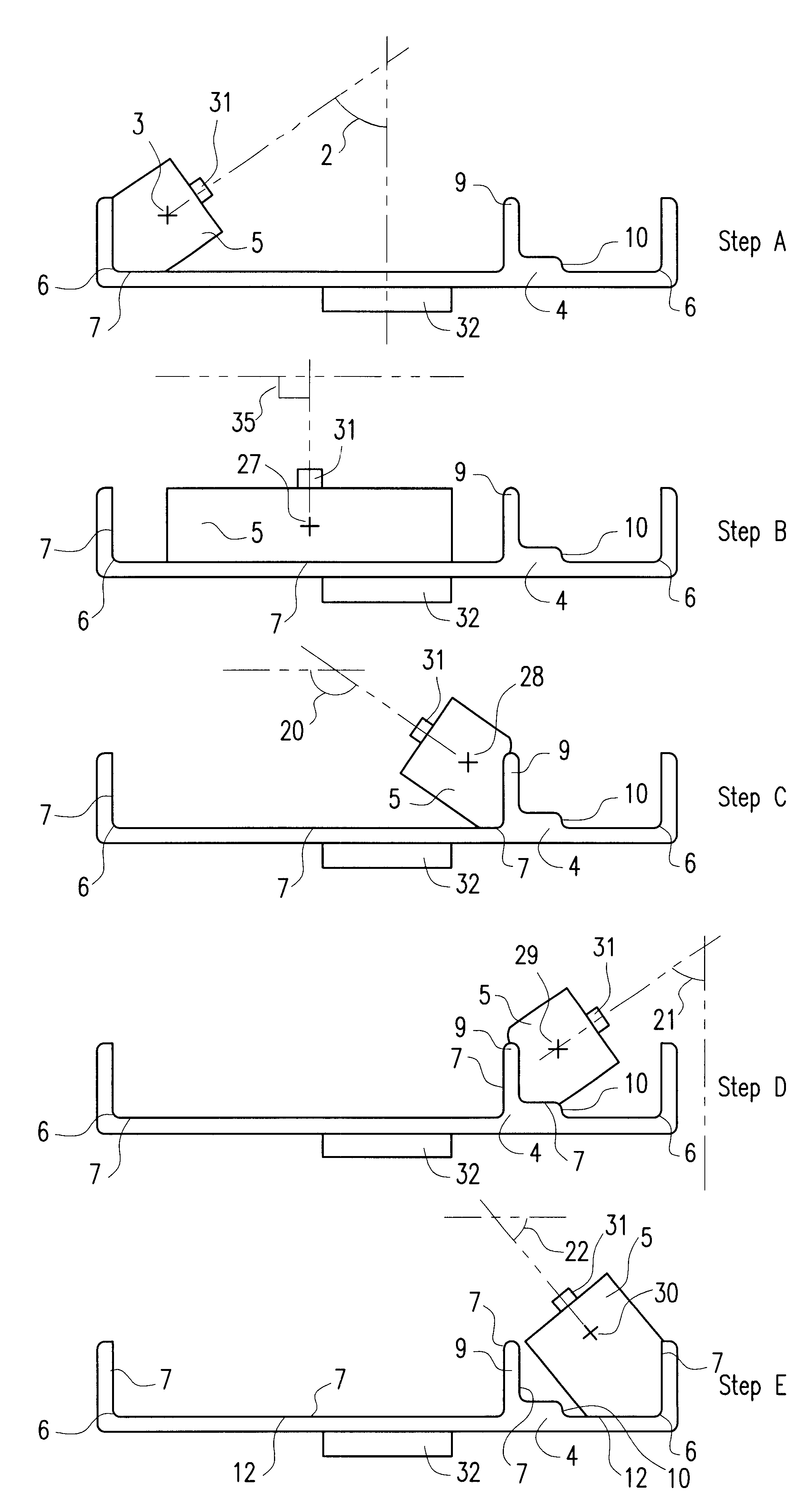
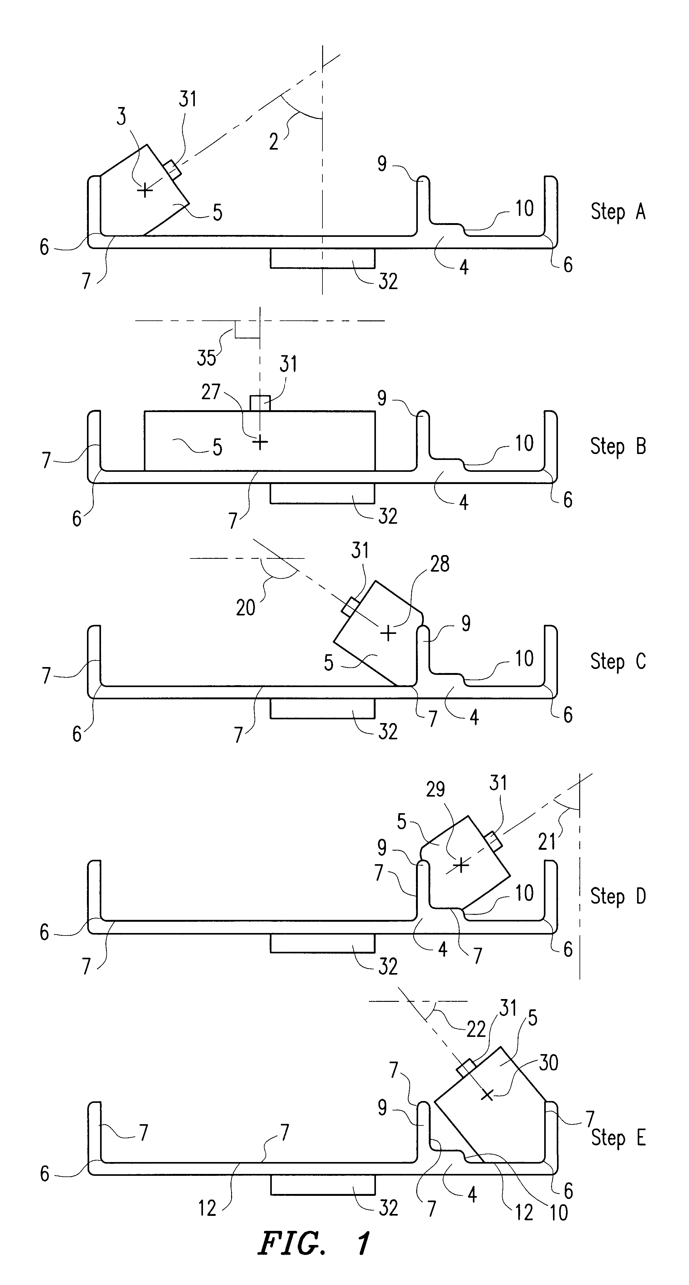
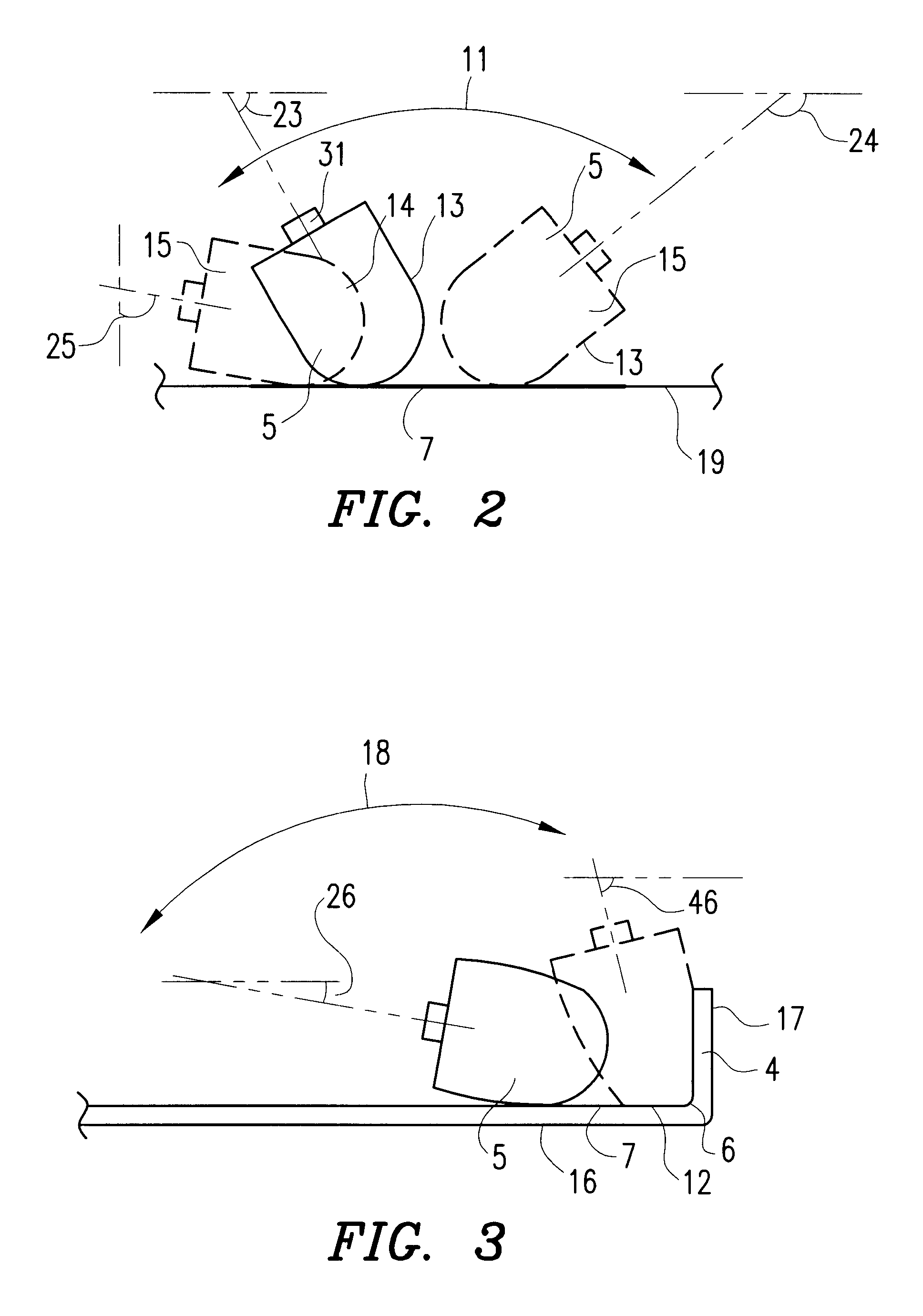
In the following description the printing method and the arrangement of the invention will first be described with reference to FIGS. 1-4 and 11-13, respectively. The printing method (i.e. tampon or screen-printing) itself is of course already known in the prior art and the description will not focus on this. After the description of the method and the arrangement to transfer a picture to an irregular surface, certain preferable printing pads (tampon pads) transferring the conductive picture colour to the detail to be shielded will be discussed together with some preferable advantageous printing colours i.e. conductive colours.

As is obvious from the embodiment illustrated in FIG. 1, the invention comprises a printing method which transfers at least two partial pictures 7 from a template 19 (cliche), and then print these partial pictures to produce a complete picture 12 on an irregular surface of a detail 4, preferably with corners 6, projections 9, stepped formation 10 or other irre...


PUM


Abstract

The present invention relates to a method and an arrangement for transferring a conductive picture (12) to an irregular surface of a mobile phone casing (4) for shielding the mobile phone casing from electromagnetic radiation. It also relates to the printing color used for the conductive picture and tampon pads (5) used for the transferring of the conductive printing color to the phone casing (4). Conductive partial pictures (7) are printed on the irregular surface of the casing (4) step by step by means of tampon pads until the complete conductive picture (12) is achieved. The tampon pad has a shape corresponding to the surface of the phone casing. The printing color has a composition, which facilitates the adhering on the tampon pad. The invention also describes a method for printing an electric circuit pattern on a phone casing (4) by using the above mentioned tampon pads and printing color.

Description

The present invention relates to a method for transferring a conductive picture to an arbitrary surface of a detail by means of a printing means, an arrangement for transferring the conductive picture to the detail, a printing colour used for the conductive picture and printing pads used for the transferring of the printing colour. It also relates to a method for printing an electrical circuit pattern on a detail, e.g. a PCB, by using a printing pad, and an apparatus having at least one electrical component to be shielded from electromagnetic radiation.It is previously known to transfer a predetermined picture to a surface by means of screen-printing or tampon printing. By means of these methods, it is also possible to print on slightly bulged surfaces. However, today's printing technique imposes strong restrictions when it comes to printing on somewhat more complicated surfaces. Such surfaces can e.g. be very bulged, arched with small radii, angled and provided with angled corners,...

Claims


Application Information

Patent Timeline
Patent Type & Authority Patents(United States)
IPC IPC(8): B41M1/40B41M3/00B41F17/00H05K3/12H05K1/00
CPCB41F17/001H05K3/1275B41M1/40H05K1/0284H05K2201/0999H05K2203/0113H05K2203/0534B41F17/16B41F17/00
Inventor HOLMBERG, PER
Owner BLACKBERRY LTD
Why Eureka
Try Eureka