Supercharge Your Innovation With Domain-Expert AI Agents!

Micropositioning system

a technology of micropositioning and positioning plates, which is applied in the field of manufacturing, can solve the problems of prohibitively expensive tooling acquisition

Inactive Publication Date: 2002-10-29
BAE SYSTEMS PLC
View PDF34 Cites 19 Cited by
  • Summary
  • Abstract
  • Description
  • Claims
  • Application Information

AI Technical Summary

Benefits of technology

The present invention seeks to alleviate the problem. of expense associated with the known tool positioning methods described above, by providing an apparatus and a method for accurately positioning tools for use in manufacturing or inspection operations whilst reducing the need for costly tooling such as jigs.
To assist the image processing system, the lighting is preferably controlled to give a high contrast between the projected image on the surface and the rest of the surface. Advantageously, the lighting is chosen to minimise unwanted reflections, shadows, and other uneven illumination.
Feedback from the servo motors allows an operator to confirm that the tool has moved to the required x, y position.
Prior to a manufacturing operation being undertaken, the micropositioning system is preferably calibrated to allow the x, y co-ordinates within the field of view of the radiation detector to be linked to the x, y position of the tool. This allows the processor, once the x, y co-ordinates of an image within the field of view of the radiation detector has been determined, to work out the distance the tool needs to move in the x and y directions in order to be positioned at the same x, y coordinates as the image.

Problems solved by technology

For smaller batches of articles, it is often prohibitively expensive to obtain the tooling, such as jigs or other fixtures, which permits highly accurate manufacture of the articles.

Method used


Image

  • Micropositioning system
  • Micropositioning system
  • Micropositioning system

Examples


Embodiment Construction

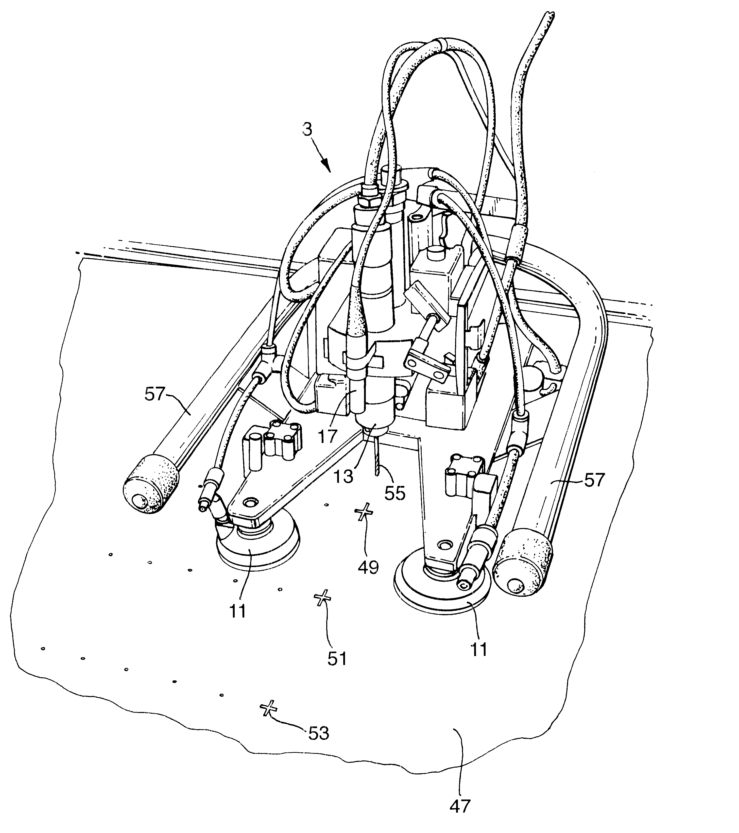
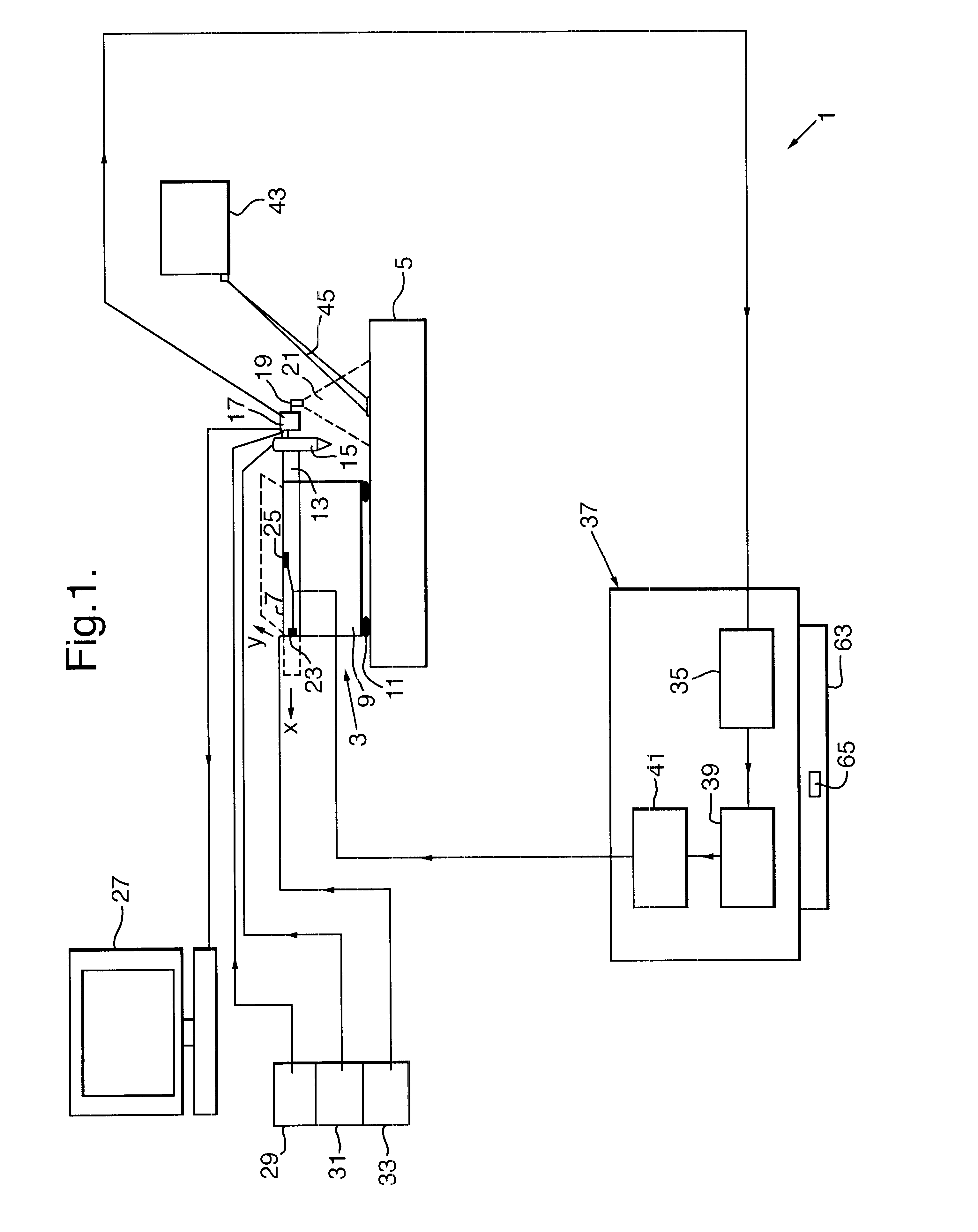
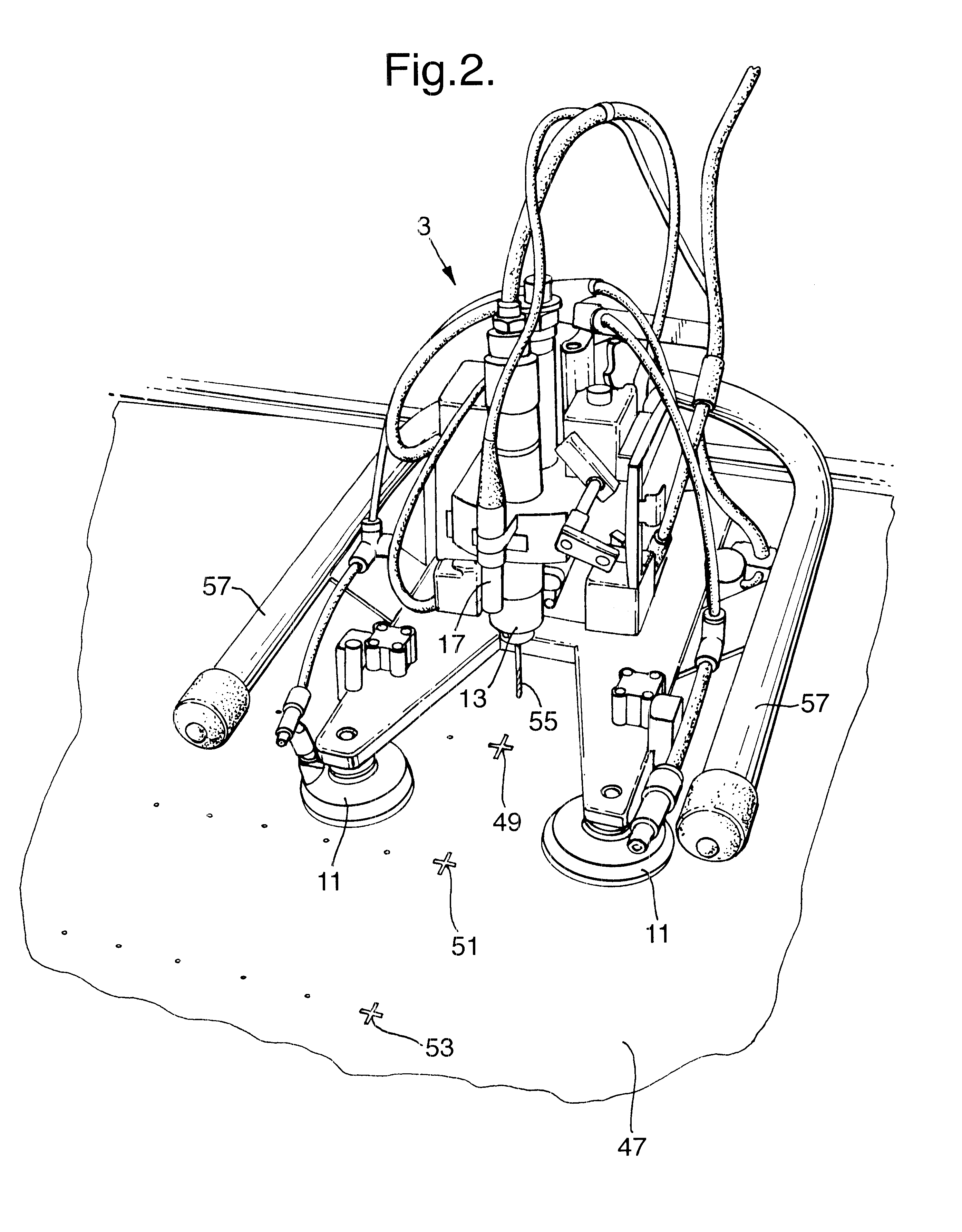
FIG. 1 shows a schematic diagram of a micropositioning system 1 in accordance with the present invention. A micropositioning unit 3 is placed on a surface 5. The surface 5 is an aircraft panel curved to match the fuselage profile, the radius of curvature being 2m. The micropositioning unit comprises a moveable stage 7 mounted on a platform 9. The platform 9 has vacuum suckers 11 attached to its underside for releasably attaching the platform 9 to the surface 5. A tool holder 13 is mounted on the moveable stage 7. A tool 15 is held in the tool holder 13. A camera 17 and a light source 19 are mounted adjacent the tool 15, the light source 19 projecting a beam 21 onto the surface 5. The moveable stage 7 is operable by an x direction servo motor 23 and a y direction servo motor 25, where the x and y directions are substantially in the same plane as the moveable stage. The camera 17 is connected to a monitor 27 and to a camera power source 29. The tool 15 is connected to a tool power sou...


PUM


Abstract

The present invention provides an apparatus and a method for accurately positioning tools for use in manufacturing or inspection operations whilst reducing the need for costly tooling such as jigs.The method for accurately positioning tools comprises at least the steps ofprojecting an image onto a surface, detecting the projected image, processing the projected image, calculating at least two dimensional co-ordinates of the projected image relative to a tool, and moving the tool so that it is positioned in a pre-defined spacial relationship with respect to the projected image.The micropositioning system comprisesa radiation source for projecting an image onto a surface, a radiation detector for detecting the projected image, tool conveyancing means for carrying a tool, processor means for calculating at least two dimensional co-ordinates of the projected image detected by the radiation detector relative to the tool, and control means for controlling the tool conveyancing means so as to position the tool in a pre-defined spacial relationship with the projected image in response to a signal from the processor means.

Description

1. Field of the InventionThis invention relates to the general field of manufacturing and more particularly to the positioning of tools for carrying out manufacturing or inspection operations.2. Discussion of Prior ArtsIn a manufacturing environment, it is generally necessary to perform operations such as measuring, drilling, cutting, countersinking, and inspecting, for example. Tools for carrying out these operations need to be positioned prior to performing their function.The accuracy with which the tools are positioned is dependent upon the level of accuracy required in the finished product. For example, in aircraft manufacture, many components need to be produced to very high standards of accuracy, and are often fitted and finished by hand to meet the required tolerances.Traditionally, articles being manufactured would be marked up by hand, to show where holes should be drilled or the material should be cut for example. This method is time consuming and costly, as it relies heav...

Claims


Application Information

Patent Timeline
Patent Type & Authority Patents(United States)
IPC IPC(8): G05B19/401G05B19/19G01B11/03G05D3/12
CPCG05B19/401
Inventor DOUGLAS, ANTHONY JJARVIS, PAUL EBEGGS, KEVIN W
Owner BAE SYSTEMS PLC
Features
  • R&D
  • Intellectual Property
  • Life Sciences
  • Materials
  • Tech Scout
  • Unparalleled Data Quality
  • Higher Quality Content
  • 60% Fewer Hallucinations
Learn More