Multiband antenna

a multi-band antenna and antenna technology, applied in the direction of antennas, antenna supports/mountings, non-resonant long antennas, etc., can solve the problems of bulky structure with its matchings, two or at the most three frequency bands that can be used, and complicated structur

Inactive Publication Date: 2002-10-29
PULSE FINLAND
View PDF15 Cites 57 Cited by
  • Summary
  • Abstract
  • Description
  • Claims
  • Application Information

AI Technical Summary

Problems solved by technology

A common drawback in arrangements according to FIG. 1 and in comparable arrangements in respect to multiband use is that there are only two or at the most three frequency bands that can be used.
It is true that by adding elements one can have as many bands as one wants, but then the structure with its matchings becomes bulky and complicated.

Method used


Image

  • Multiband antenna
  • Multiband antenna
  • Multiband antenna

Examples


Embodiment Construction

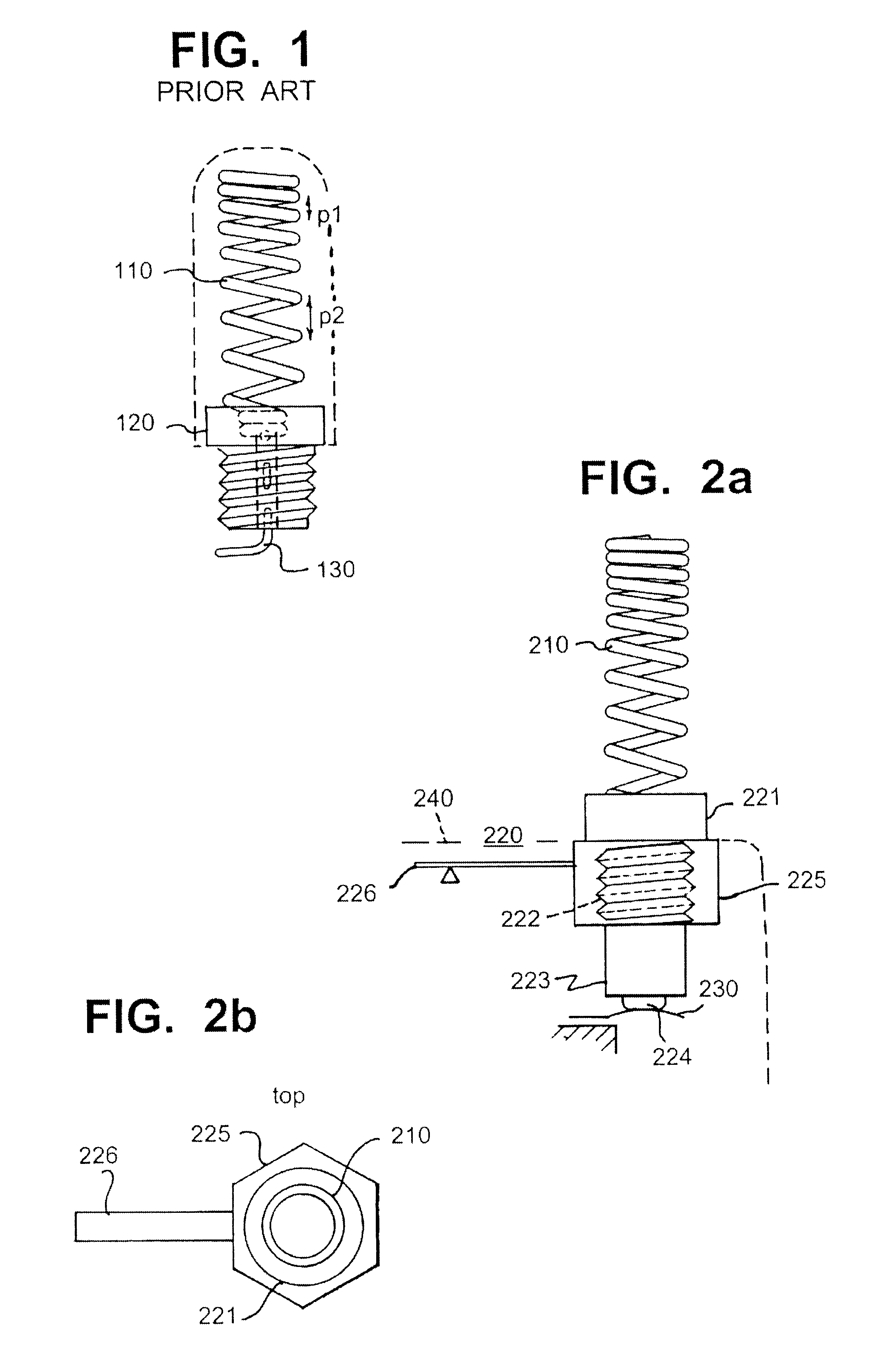
FIG. 1 was already discussed in connection with the description of the prior art.

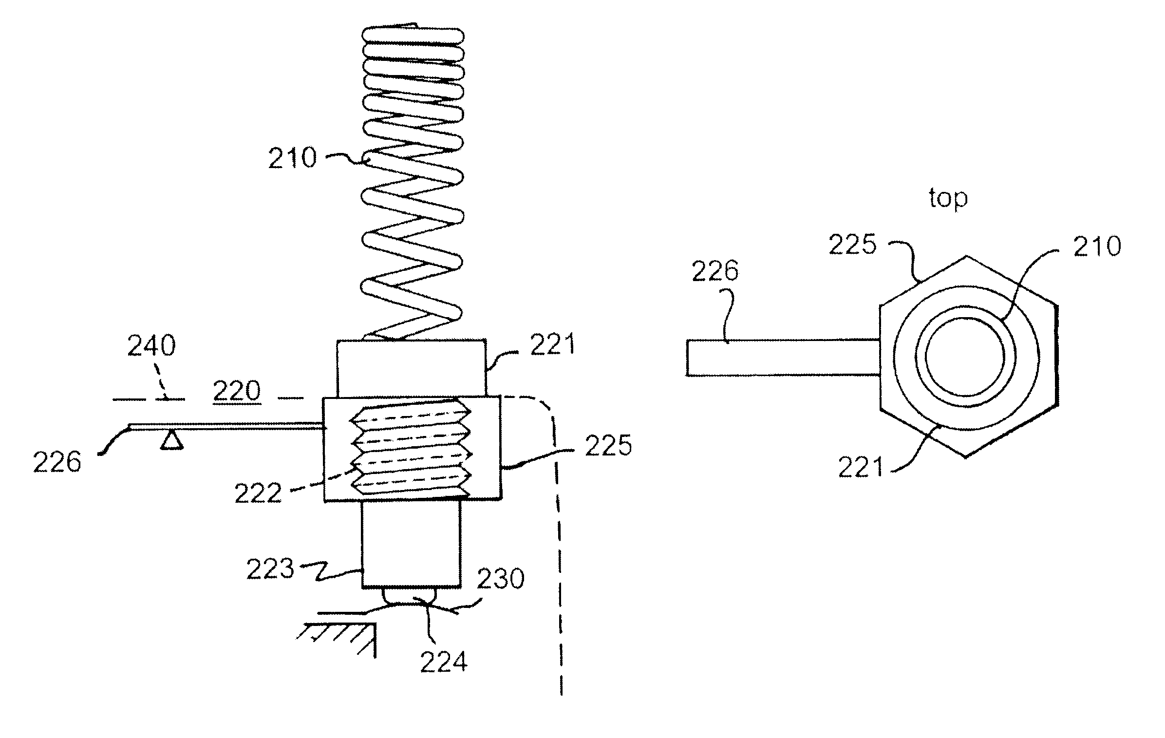
FIG. 2a shows a side view of an example of the antenna structure according to the invention. It comprises a helix-type antenna element 210, joining piece 220, and antenna feed conductor 230. Like in the structure shown in FIG. 1, the pitch in the helix element gets smaller from the lower end to the upper end of the element. Terms "lower", "upper", "horizontal" and "vertical" refer in this description and in the claims to the position of the antenna structure as shown in FIG. 2, and they have nothing to do with the operating position of the antenna. The joining piece 220 comprises a top part 221, thread part 222, bottom part 223, connecting part 224, counterpart 225, and a projecting part 226. All these parts are conductive and in galvanic contact with each other. The horizontal projection 226 is attached by its one end to the counterpart 225. It may be e.g. a separate flat plate or just a metal plating ...


PUM


Abstract

The invention relates to a multiband antenna structure suitable for mobile stations in particular. The radiating elements of the antenna include not only a helix (210) but also the joining piece (220) that attaches the helix to the apparatus. The helix is shaped such that the distance between its conductor turns varies. The electrical length of the joining piece is increased e.g. by means of a conductive projection (226) that remains within the covering of the apparatus. By suitably dimensioning the parts, at least five of the resonances that the helix and joining piece have together and separately are arranged at useful points on the frequency scale. The structure according to the invention is despite the several bands simple and relatively low in production costs.

Description

1. Field of UseThe invention relates to a multiband antenna structure suitable for mobile stations in particular.2. Description of Related ArtThe development in mobile stations is leading towards apparatuses functioning in a plurality of frequency bands. At first, mobile phones operated each in one frequency band only. Then, models functioning in two frequency bands, such as GSM900 and GSM1800 systems, were introduced into the market. The introduction of WCDMA (wideband code division multiple access) technology and extension of the GSM (global system for mobile communications) technology into the frequency band earlier used by the NMT450 system result in the manufacture of models functioning in even more bands. This means additional requirements accordingly on the antennas of the mobile communication devices in question.From the prior art it is known several antenna structures functioning in at least two frequency bands. These structures usually comprise two parts arranged to resona...

Claims


Application Information

Patent Timeline
Patent Type & Authority Patents(United States)
IPC IPC(8): H01Q1/24H01Q11/08H01Q1/36H01Q5/00H01Q9/40H01Q9/04H01Q11/00H01Q5/357
CPCH01Q1/243H01Q5/357H01Q9/40H01Q1/362
Inventor ANNAMAA, PETTERI
Owner PULSE FINLAND
Why Eureka
Try Eureka