
Method for regulating a three-phase machine without a mechanical rotary transducer

a technology of rotary transducer and three-phase machine, which is applied in the direction of dynamo-electric gear control, electric generator control, electrical apparatus, etc., can solve the problems of inability to measure the current space phasor, inability to detect at least two phase currents using expensive phase current sensors, and inability to use current detection methods based on em

Inactive Publication Date: 2002-11-12
SCHRODL MANFRED
View PDF26 Cites 6 Cited by
  • Summary
  • Abstract
  • Description
  • Claims
  • Application Information

AI Technical Summary

Benefits of technology

In accordance with a special feature of the invention, at least two measurements of the increase in D.C. link current are carried out, and the measured values of the two increases are entered into the stator voltage equations and linked mathematically. An important advantage of this method according to the invention is the fact that the same measuring module is always used, so that errors of measurement due to component leakage, etc., are compensated by the combination of several measurements and thus do not affect the result. With this embodiment of the invention with the combination of two measurements, the EMC can be eliminated and the conductivity measurement is therefore independent of speed. This is not possible in measurement of the current space phasor for at least two phase currents, since the involved current sensors have different errors of measurement that affect the result.

Problems solved by technology

At low flux rates, the flux detection methods based on EMC fail.
The disadvantage of the method described there lies in the fact that for detection of the current space phasor the detection of at least two phase currents using expensive phase current sensors, e.g. transfo-shunts, is necessary.
This is not possible in measurement of the current space phasor for at least two phase currents, since the involved current sensors have different errors of measurement that affect the result.

Method used


Image

  • Method for regulating a three-phase machine without a mechanical rotary transducer
  • Method for regulating a three-phase machine without a mechanical rotary transducer

Examples


Embodiment Construction

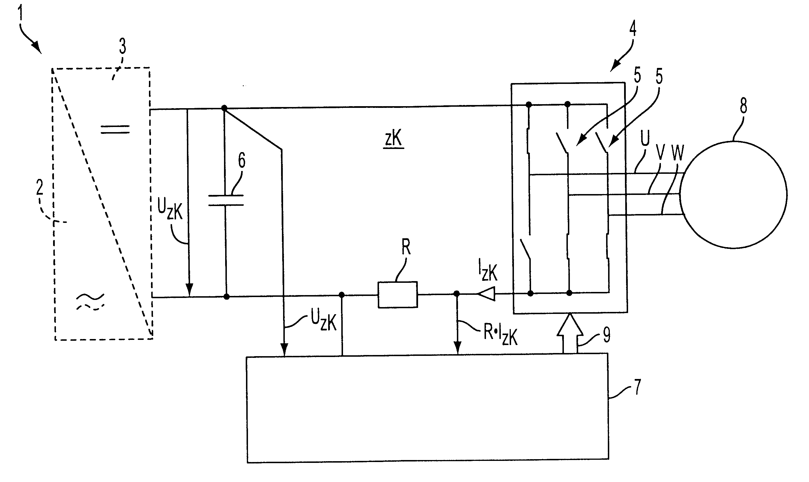
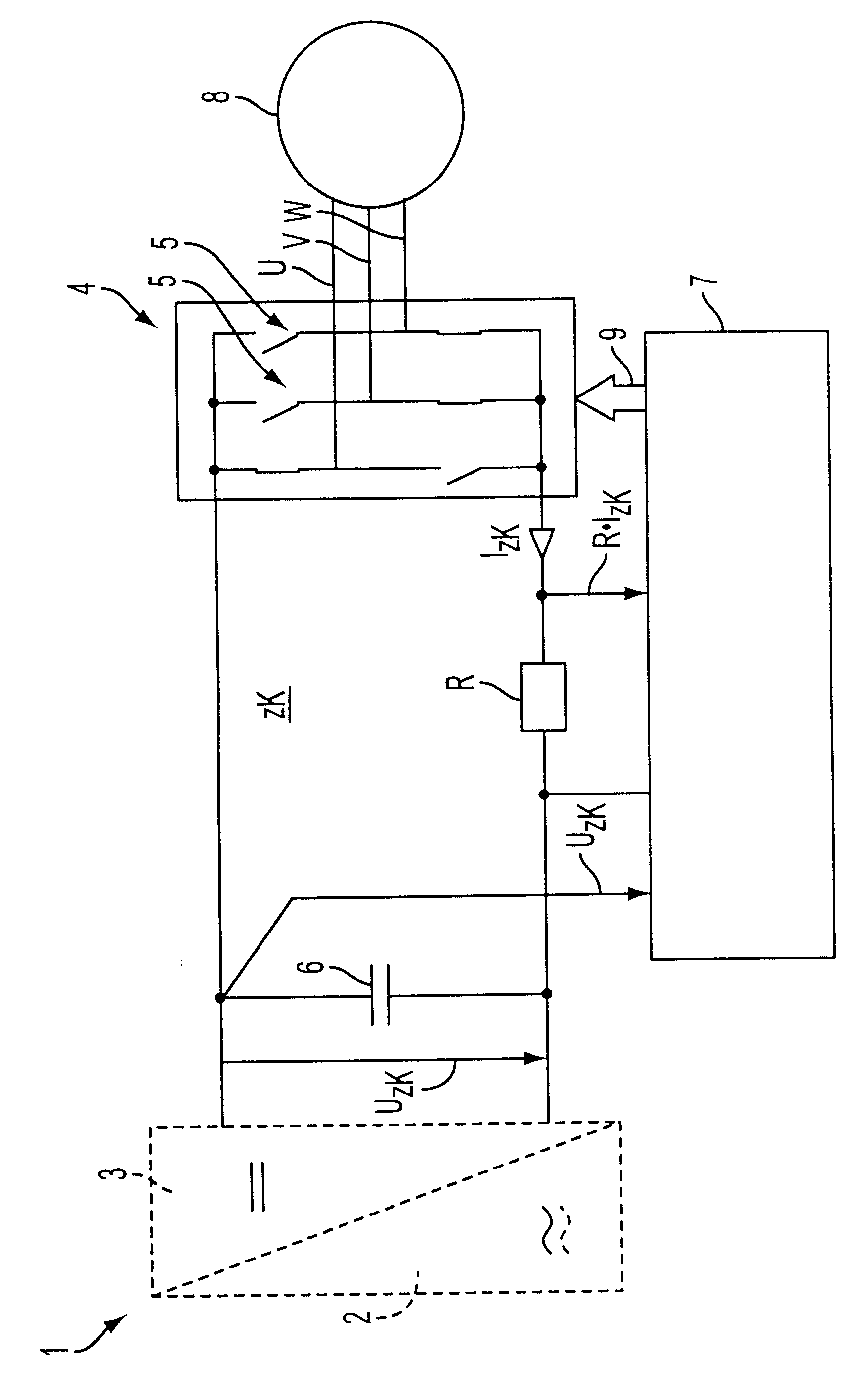
In accordance with the FIGURE, an inverter 1 is supplied by a one- or three-phase A.C. power system at the optional A.C. input 2. The D.C. side 3 is connected to the converter 4, which has the semiconductor valves 5, by the D.C. link zk. The D.C. link voltage Uzk of the measuring and control unit 7 is fed by a capacitor 6. Moreover, the D.C. link current Izk of the measuring and control unit 7 is also fed by the resistor R. The actual switching state of the inverter I is also detected by the measuring and control unit 7. The three-phase machine 8 to be regulated is connected on the bridge circuit of the semiconductor valves 5. The converter 4 is controlled by means of the control signals 9 calculated by the measuring and control unit 7.

In conclusion, it is noted that in the various described embodiments the same parts are allocated the same reference numbers and the same component names, whereby the disclosures contained throughout the description can be applied by analogy to the sa...


PUM


Abstract

A method is provided for regulating a three-phase machine functioning under any operational conditions without a mechanical rotary transducer. The machine is supplied with D.C. power by an inverter, where parameters of a D.C. link using an actual switching state of the inverter are detected for regulation. The method includes measuring (1) flow direction required for field-oriented control in asynchronous machines, and (2) rotor position for rotor-oriented control in synchronous machines. The measuring is performed by using spatial magnetic conductivity fluctuations in the machine. The conductivity fluctuations are detected using parameters for a D.C. link. An actual switching state of an inverter is used in the measuring process. Mathematical evaluation to calculate flow direction or rotor direction is then performed.

Description

Field of the InventionThe invention relates to a method for regulating a three-phase machine without a mechanical rotary transducer, in particular an asynchronous or synchronous machine, functioning under any operational conditions.For high-precision regulation of three-phase machines, in particular asynchronous and synchronous machines, the latter either with permanent magnet excitation, through reluctance effect, i.e. different magnetic conductivity depending on the rotor position, or through a combination of permanent magnet excitation and reluctance effect, the position of the magnetic flux is used. For machine speeds above a certain minimum flux rate, the induced electric current (EMC) can be detected by various methods described in the literature, and from it the flux position can be determined. At low flux rates, the flux detection methods based on EMC fail. In this case methods can be used which detect the position or flux density-related magnetic conductivity in real-time, ...

Claims


Application Information

Patent Timeline
Patent Type & Authority Patents(United States)
IPC IPC(8): H02P21/14H02P21/18H02P21/24
CPCH02P21/0039H02P21/146H02P21/24H02P21/18
Inventor SCHRODL, MANFRED
Owner SCHRODL MANFRED
Learn More