Apparatus for determining a failure of wheel speed sensors

a technology of speed sensor and apparatus, which is applied in the field of apparatus for determining the failure can solve the problems of erroneous determination of normal/abnormality of wheel speed sensor, method has not yet been established, and the failure of the device, so as to avoid the failure. the effect of erroneous determination

Inactive Publication Date: 2002-11-12
HONDA MOTOR CO LTD
View PDF8 Cites 26 Cited by
  • Summary
  • Abstract
  • Description
  • Claims
  • Application Information

AI Technical Summary

Benefits of technology

According to this apparatus, the traveling determination means determines whether or not the vehicle is traveling based on the engine rotational speed and the input-output rotational speed ratio of the torque converter when the automatic transmission is in a traveling range. When the vehicle is traveling, the engine rotational speed is in a range of values equal to or greater than a lower limit value to prevent an engine stall. Further, when the automatic transmission is in a traveling range, the rotational speed of an output shaft of the torque converter is in a range of values equal to or greater than a predetermined value since the output shaft is rigidly connected to drive wheels. Therefore, the input-output rotational speed ratio of the torque converter, which is a ratio between the rotational speed of the output shaft and that of an input shaft of the torque converter, i.e., the engine rotational speed, is also in a range of values equal to or larger than a predetermined value. Therefore, by determining whether the vehicle is traveling as described above, it is possible to appropriately determine whether or not the vehicle is actually traveling.
Further, in the apparatus of the invention, when it is determined by the traveling determination means that the vehicle is running, the sensor failure determination means determines that the wheel speed detection system including the wheel speed sensors has failed, on condition that at least one of the wheel speeds detected by the wheel speed sensors indicates a stopped state of a corresponding wheel. This condition or assumed state is an abnormal one in which at least one of the wheel speeds indicates a stopped state of a wheel when the vehicle is actually running. Therefore, by the above failure determination, it is possible to appropriately detect occurrence of a failure of a wheel speed sensor itself, and that of a failure of the wheel speed detection system including the wheel speed sensors, due to disconnection of a coupler of a harness, breaking of a wire, or the like. Further, when the vehicle is actually standing or stopped, this state of the vehicle is properly determined by the traveling determination means, thereby inhibiting the sensor failure determination means from carrying out the failure determination. This makes it is possible to reliably avoid erroneous determination of a failure of the wheel speed sensors, when they are normally operating.

Problems solved by technology

In the conventional torque distribution system, however, the method of distinguishing between causes of this state has not yet been established, that is, a method has not yet been established for determining whether the above state is caused by an actually stopped state of the vehicle or by a failure of the wheel speed sensors due to disconnection of the coupler of the harness or the like.
This can result in an erroneous determination of normality / abnormality of the wheel speed sensors.
Further, when the vehicle is actually standing or stopped, this state of the vehicle is properly determined by the traveling determination means, thereby inhibiting the sensor failure determination means from carrying out the failure determination.
Immediately after the automatic transmission has entered the traveling range from the neutral state, stirring of oil in the torque converter increases an amount of change in the input-output rotational speed ratio of the torque converter, thereby making the input-output rotational speed ratio unstable.
This can prevent appropriate execution of traveling determination which is carried out based on the unstable input-output rotational speed ratio.

Method used


Image

  • Apparatus for determining a failure of wheel speed sensors
  • Apparatus for determining a failure of wheel speed sensors
  • Apparatus for determining a failure of wheel speed sensors

Examples


Embodiment Construction

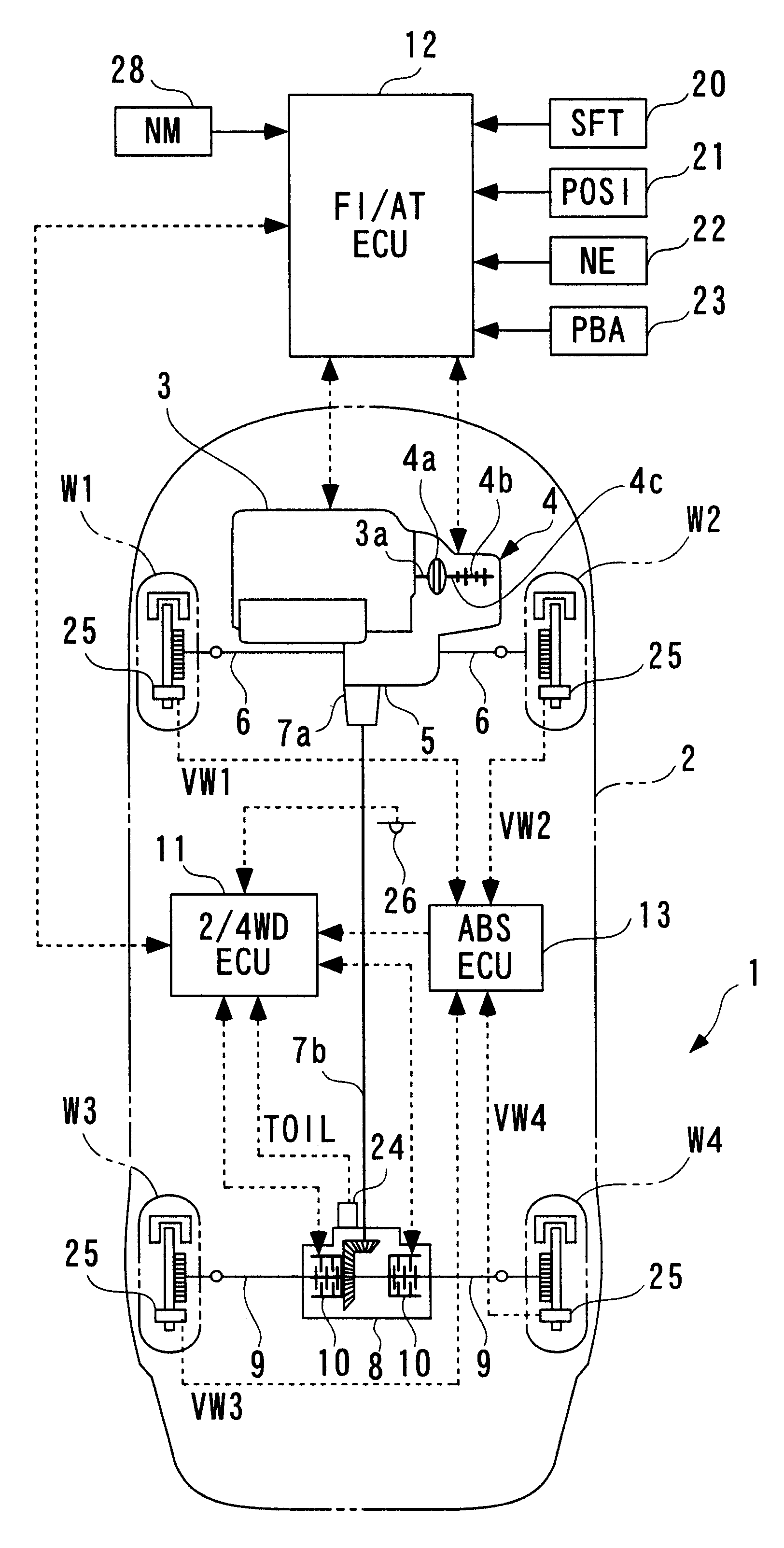
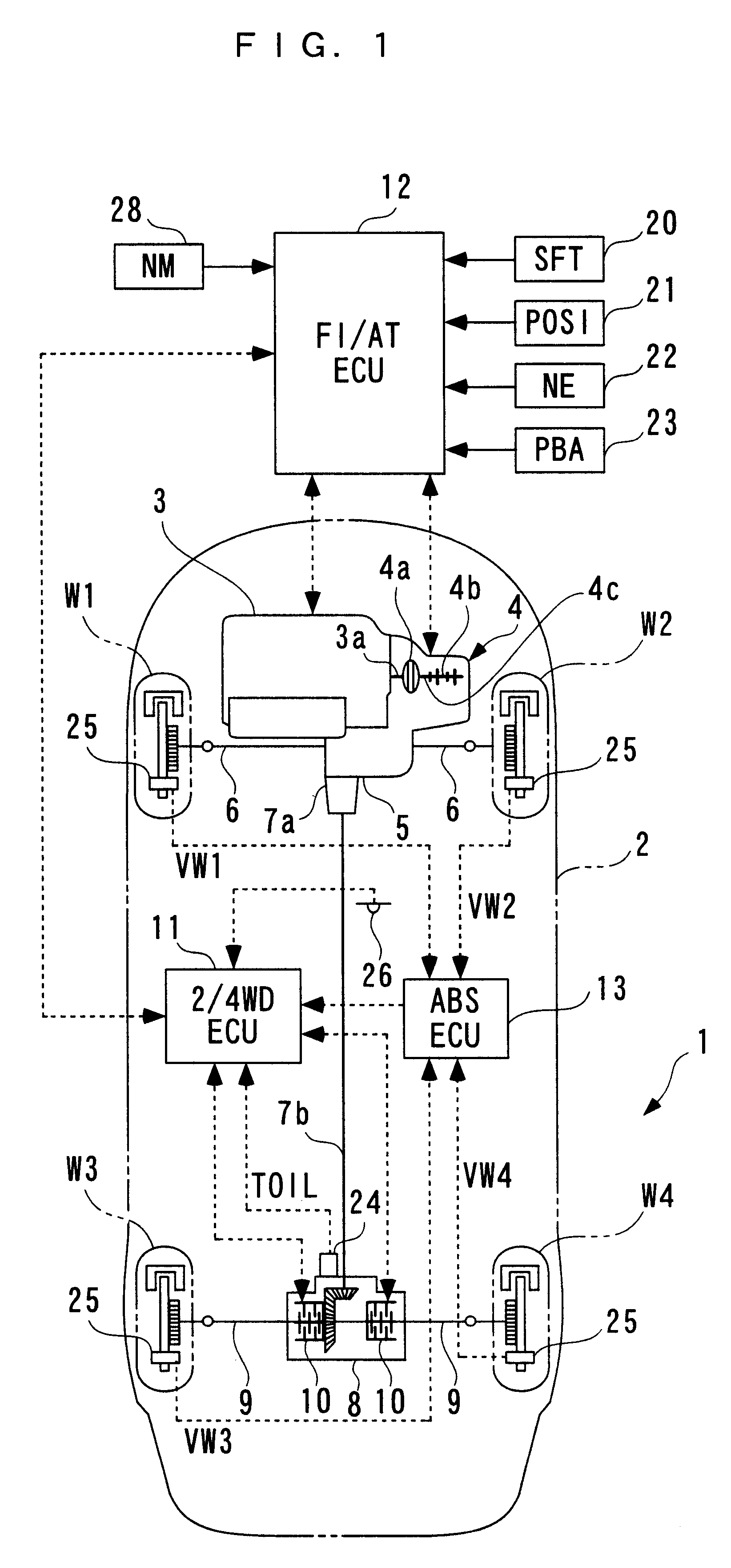
The invention will now be described in detail with reference to the drawings showing an embodiment thereof. Referring first to FIG. 1, there is schematically shown the arrangement of a four-wheel-drive vehicle 2 to which is applied an apparatus for determining a failure of wheel speed sensors, according to the invention. As shown in the figure, this four-wheel-drive vehicle (hereinafter referred to as "the vehicle") 2 includes an engine 3 transversely mounted in a front part thereof and an automatic transmission 4 associated with the engine 3.

The automatic transmission 4 includes a torque converter 4a for transmitting an output power or torque of the engine 3 to the automatic transmission 4, a shift lever, not shown, which is capable of selecting any one of eight shift positions consisting of "1, 2, 3, D4, D5, N, R, P", and a gear mechanism 4b, partly shown, which can be shifted to any of six gear positions having respective change gear ratios, i.e., first to fifth speed gear positi...


PUM


Abstract

An apparatus for determining a failure of wheel speed sensors, which is capable of properly determining whether or not a wheel speed detection system including the wheel speed sensors has failed, if at least a wheel speed detected by the wheel speed sensors indicates a stopped state of a corresponding wheel. An engine rotational speed is detected, and an input-output rotational speed ratio of a torque converter of an automatic transmission mounted in the vehicle is calculated. A shift range of the automatic transmission is detected. Whether or not the vehicle is traveling is determined based on the engine rotational speed and the input-output rotational speed ratio when the automatic transmission is in a traveling range. It is determined that the wheel speed detection system including the wheel speed sensors has failed, if it is determined that the vehicle is traveling, and at the same time, at least one of wheel speed sensors indicates a stopped state of a corresponding one of the wheels.

Description

1. Field of the InventionThis invention relates to an apparatus for determining a failure of wheel speed sensors that detect wheel speeds of respective wheels of a vehicle for control of torques transmitted to at least two of the wheels.2. Description of the Prior ArtConventionally, it is well-known to control torques transmitted to wheels in dependence on the wheel speeds of respective wheels detected by wheel speed sensors of the vehicle. For instance, Japanese Laid-Open Patent Publication (Kokai) No. 6-72171 discloses a technique concerning a torque distribution system for a four-wheel drive vehicle. According to this technique, the engagement force of a clutch which changes the torque distribution between front and rear wheels is controlled depending on the wheel speeds of the four front and rear wheels detected by the wheel speed sensors. More specifically, wheel speed signals indicative of the respective wheel speeds sensed by the wheel speed sensors are input to a 4WD-ECU, to...

Claims


Application Information

Patent Timeline
Patent Type & Authority Patents(United States)
IPC IPC(8): G05B9/02F16H59/38F16H59/40G01P3/42B60T8/88F16H59/44
CPCG05B9/02F16H59/40Y10T74/1926
Inventor NISHIDA, KENZONIHANDA, NORIHISA
Owner HONDA MOTOR CO LTD
Why Eureka
Try Eureka