Tunnel magnetoresistance effect element

a technology of magnetoresistance effect and element, which is applied in the field of tunnel magnetoresistance effect element, can solve the problems of leakage current through pinholes, inability to achieve greater output, and inability to obtain outpu

Inactive Publication Date: 2002-11-19
TDK CORPARATION
View PDF25 Cites 47 Cited by
  • Summary
  • Abstract
  • Description
  • Claims
  • Application Information

AI Technical Summary

Problems solved by technology

When the surface is not smooth enough while the thickness of the barrier layer is thin, pinholes are apt to occur in a portion of the barrier layer, and a leakage current may occur through the pinholes.
When the leakage current occurs, the greater output can not be achieved.
Further, an output may not be obtained when an amount of leakage current is too large.
Under the foregoing circumstances, a feasibility study for realizing a tunnel magnetoresistance effect element including a head configuration has not been sufficiently achieved, though such a feasibility study is in the initial stage.
However, if the thickness becomes thin enough to cause pin holes, a leakage current is generated, which is not preferable.
Actually, the size of an element is very small, therefore, in some cases, measurement length may not be long enough.
As to the prior art using abrading method, which employs abrasive liquid containing alumina abrasive grain or colloidal silica, it is very difficult to achieve the surface condition defined in the present invention, therefore, it is hard to realize.
In contrast, if the value of D increases to exceed 0.3 .mu.m, an effective track width is unfavorably expanded to result in failure to meet with the requirement of high density recording in the future.

Method used


Image

  • Tunnel magnetoresistance effect element
  • Tunnel magnetoresistance effect element
  • Tunnel magnetoresistance effect element

Examples


Embodiment Construction

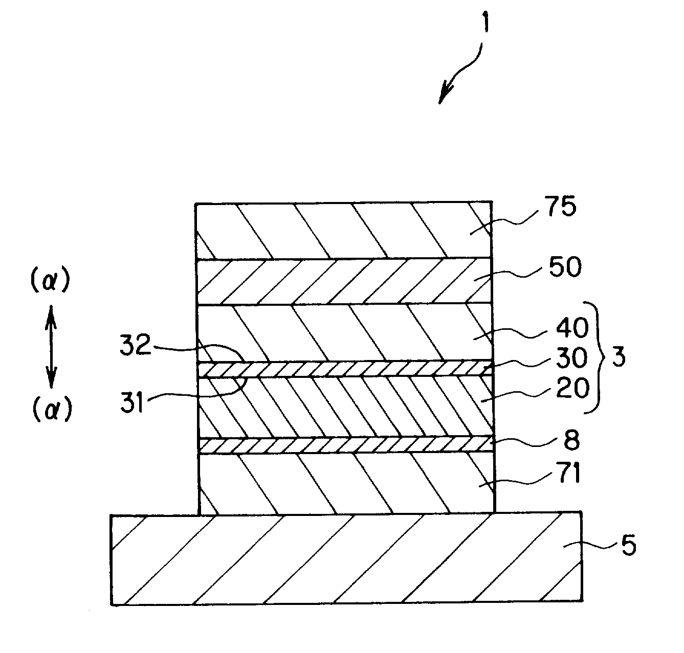
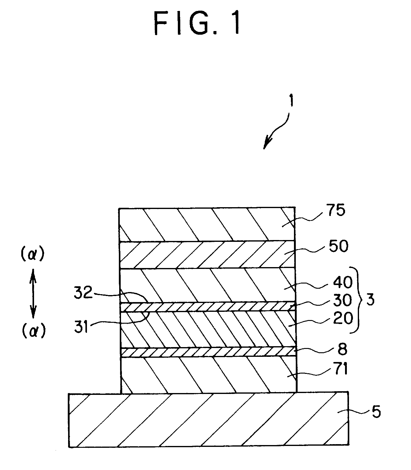
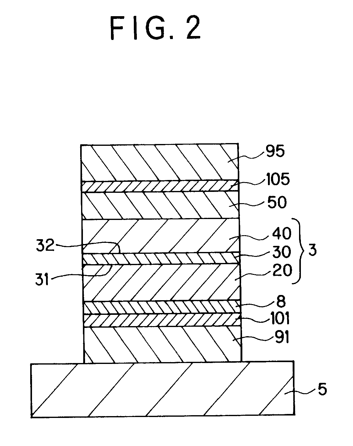
Ferromagnetic tunnel magnetoresistance effect element samples shown below were prepared. Specifically, each sample was prepared by stacking an electrode layer 71 (Cu; 700 .ANG. in thickness), an under layer (Ta; 100 .ANG. in thickness), a ferromagnetic layer 20 (laminate body of NiFe layer (100 .ANG. in thickness) and CoFe layer (20 .ANG. in thickness)) serving as a free layer, a tunnel barrier layer 30 (aluminum oxide; 10 .ANG. in thickness), a pinned ferromagnetic layer 40 (CoFe; 30 .ANG. in thickness) whose magnetization direction is fixed in a detection magnetic field direction, a pinning layer 50 (RuRhMn; 100 .ANG. in thickness) for pinning magnetization of the ferromagnetic layer 40, and an electrode layer 75 (Ta; 50 .ANG. in thickness), in the order named on a substrate (AlTiC with Al.sub.2 O.sub.3). The size of each sample was 1 .mu.m.times.1 .mu.m.

In the samples, the surface roughness of the tunnel barrier layers was changed using the foregoing techniques (i) to (v).

When me...


PUM

PropertyMeasurementUnit
roughnessaaaaaaaaaa
height Rmaxaaaaaaaaaa

Abstract

In a tunnel magnetoresistance effect element comprising a tunnel multilayered film having a tunnel barrier layer, a ferromagnetic free layer and a ferromagnetic pinned layer such that the tunnel barrier layer is held between the ferromagnetic free layer and the ferromagnetic pinned layer, three indexes representing a surface roughness state of the tunnel barrier layer are set such that Ra<=1 nm, Rmax<=10 nm and Rrms<=1.2 nm, wherein Ra is one of the three indexes and representing the center line average roughness, Rmax is one of the three indexes and representing the maximum height, and Rrms is one of the three indexes and representing the standard deviation roughness. Thus, the tunnel magnetoresistance effect element exhibits improved characteristics, particularly, a large head output.

Description

1. Field of the InventionThe present invention relates to a tunnel magnetoresistance effect element. The ferromagnetic tunnel magnetoresistance effect element is, among magnetoresistance effect films for reading the magnetic field intensity of a magnetic recording medium or the like as a signal, an element which is capable of reading a small magnetic field change as a greater electrical resistance change signal. The ferromagnetic tunnel magnetoresistance effect element is mainly incorporated in, for example, a hard disk drive.2. Description of the Related ArtFollowing the high densification of hard disks (HD), highly sensitive magnetic heads with high outputs have been demanded. In response to these demands, attention has been paid to a ferromagnetic tunnel magnetoresistance effect element having a multilayered structure composed of ferromagnetic layer / tunnel barrier layer / ferromagnetic layer, which utilizes a ferromagnetic tunnel magnetoresistance effect.The ferromagnetic tunnel ma...

Claims


Application Information

Patent Timeline
Patent Type & Authority Patents(United States)
IPC IPC(8): G11B5/39H01L43/08G01R33/09H01F10/26
CPCG11B5/3903H01L43/08Y10T428/24355H10N50/10
Inventor ARAKI, SATORUSHIMAZAWA, KOJIMORITA, HARUYUKI
Owner TDK CORPARATION
Why Eureka
Try Eureka