Protecting unit

a protection unit and unit technology, applied in the field of protection units, can solve problems such as serious accidents, high-speed transmission difficulties, and serious accidents

Inactive Publication Date: 2002-11-26
KK TOSHIBA
View PDF8 Cites 24 Cited by
  • Summary
  • Abstract
  • Description
  • Claims
  • Application Information

AI Technical Summary

Problems solved by technology

Though the LVDS is suitable for the high-speed transmission, when used in the data transmission from the image processor to the laser driver, there occurs a big problem.
Accordingly, in the worst case situation, the laser is always in an emitting state to result in liability to serious accidents.
However, the high-speed transmission becomes difficult.
Thus, when with the aforementioned existing LVDS, signal that drives the laser diode is transmitted / received, a serious accident may occur.
On the other hand, when the unbalanced signal, instead of the LVDS, is used in the data transmission, the high-speed data transmission can not be realized.

Method used


Image

  • Protecting unit
  • Protecting unit
  • Protecting unit

Examples


first embodiment

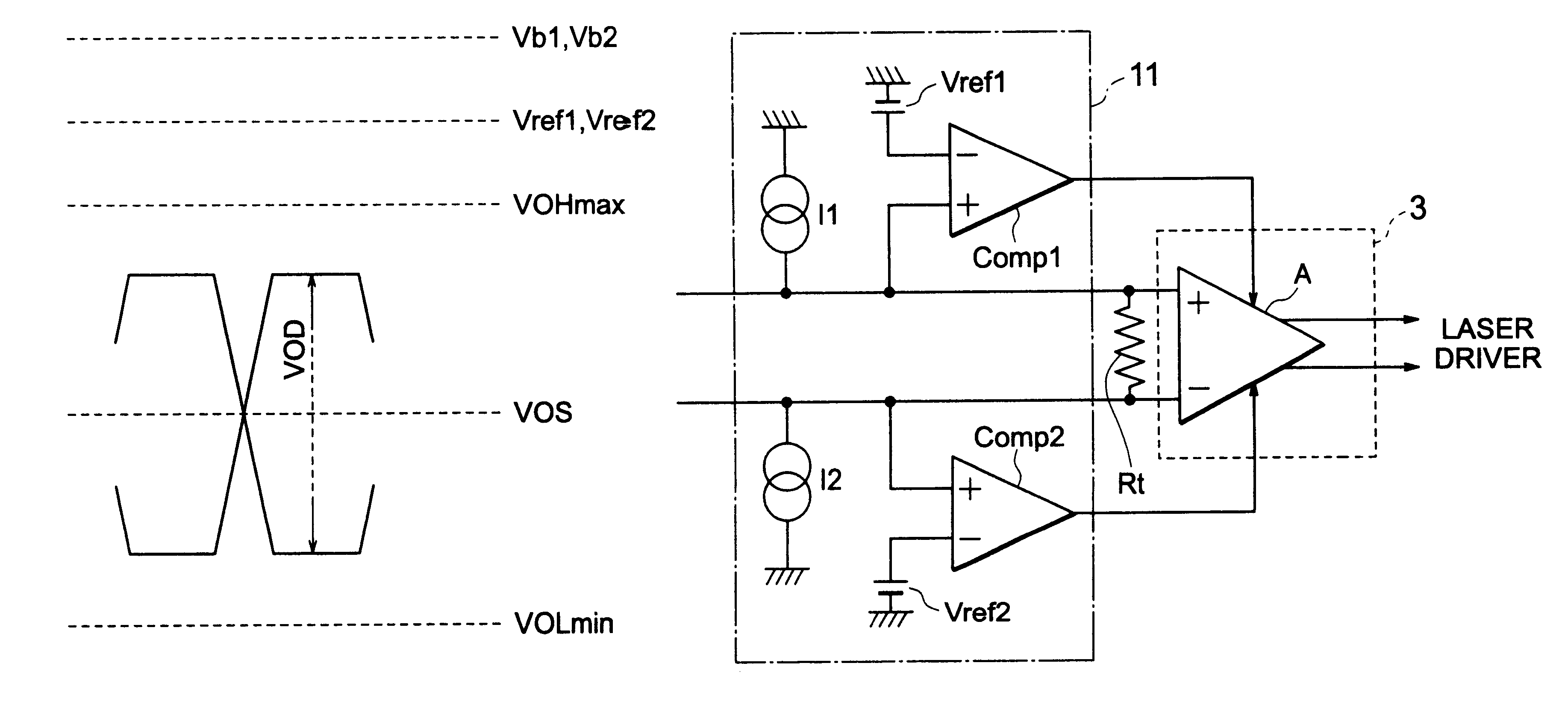
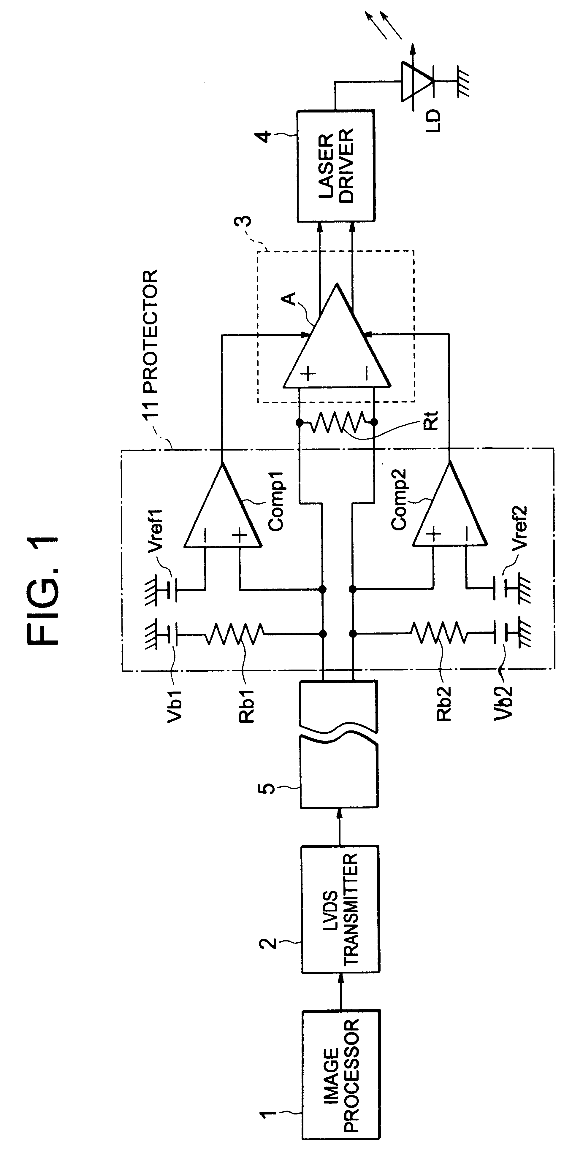
In the following, embodiments of the present invention will be explained in more detail with reference to the drawings. FIG. 1 is a system diagram for explaining the present invention. Further, in FIG. 1, constituents identical with those of FIG. 6 are given the same reference numerals to explain.

In FIG. 1, an image processor 1 processes image information such as read-in characters to convert into printing data. The printing data are supplied to a LVDS transmitter 2. The LVDS transmitter 2 converts the printing data into balanced signal of small signal amplitude, the converted printing data being supplied to a LVDS receiver 3 and a protector 11 through a cable 5. That is, the converted printing data are supplied to the protector 11 and at the same time to the LVDS receiver 3 constituted of a differential input / output amplifier A. Output of the LVDS receiver 3 is supplied to a laser driver 4, a laser diode LD being driven by the laser driver 4. A terminal resistance Rt is connected t...

second embodiment

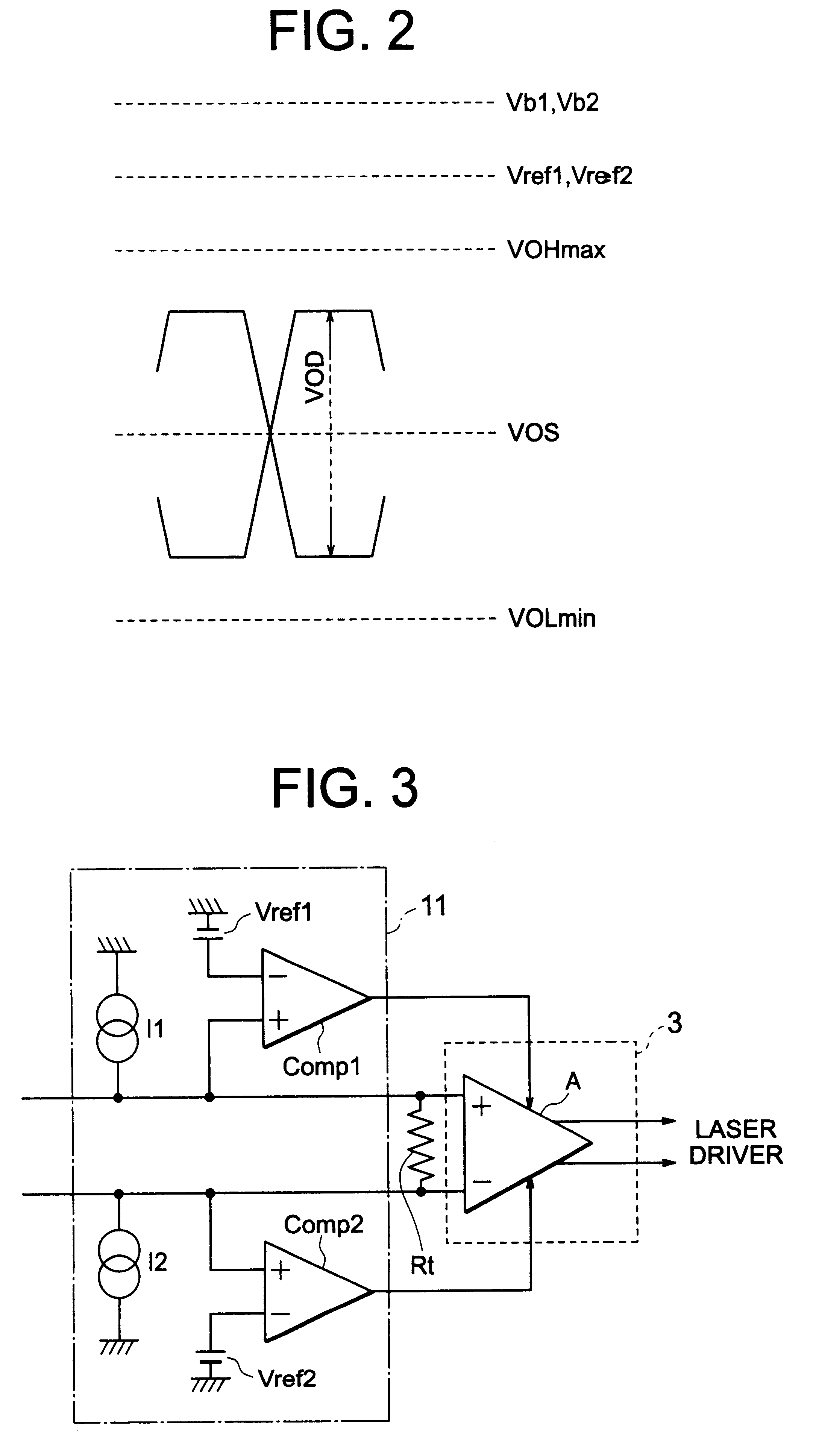
FIG. 3 is a circuit diagram for explaining the present invention. In the present embodiment, in FIG. 1, only the bias circuits that are constituted of the resistance Rb1 and voltage source Vb1 of the protector 11, and resistance Rb2 and voltage source Vb2 thereof respectively are changed to current sources I1 and I2. In FIG. 3, only the protector 11 and the LVDS receiver 3 are shown for explanation.

Upon constituting thus, compared with the case of FIG. 1, an input impedance seeing in the differential input / output amplifier A side from the input end increases. In this case, when the input end becomes an open state, due to action of the current sources I1 and I2, the voltage at the input terminal of the LVDS receiver 3 becomes to the upper limit (for instance, source voltage of the protector 11). Since the range of variation between during being open and during being normal becomes larger, detection can be implemented more surely.

In the present embodiment too, the reference voltage so...

third embodiment

FIG. 4 is a circuit diagram for explaining the present invention. Whereas FIGS. 1 and 3 judge with the voltages at the input terminals of the LVDS receiver 3, the present embodiment detects the open state of the input end by the current flowing in or out the input end of the protector 11. FIG. 4 shows only the protector 11 and the LVDS receiver 3 for explanation.

In the configuration of FIG. 4, the protector 11 is one due to current to voltage conversion. That is, a common base of transistors Q1 and Q2 is connected to a bias voltage source Vb3, the respective current sources Ie1 and Ie2 being connected to each emitter thereof, collectors thereof being connected to a bias voltage source Vb4 through each resistance RL1 and RL2. Thereby, a common base circuit is constituted. Here, input ends thereof are connected to emitters of transistors Q1 and Q2 through resistance Ri1 and Ri2 respectively, collector outputs of the transistor Q1 and Q2 being inputs of the differential input / output am...


PUM


Abstract

A protecting unit is provided. The protecting unit can prevent accidents from occurring that become problems when data are transmitted due to for instance LVDS and for instance laser light is emitted based on the data. The protecting unit is applied in an instrument comprising an input end to which differential signal is transmitted, the input end being attachable to and detachable from an input line. Here, the voltage at the input end when the input line is not connected is set to a voltage different from that generated at the input end when the input line is connected, variation of the voltage at the input end is transmitted to an input terminal of a differential input/output circuit, and the voltage at the input end or a portion corresponding thereto is compared with a prescribed voltage to fix a state of output of the differential input/output circuit to a prescribed state based on the compared results.

Description

1. Field of the InventionThe present invention relates to a protecting unit for preventing an accident particularly during an extraordinary state from occurring in an electronic instrument using for instance laser.2. Description of the Related ArtIn PPCs (Plain Paper Copiers) and laser printers, printing is carried out with laser light of a laser diode. The laser light is irradiated onto for instance portions to be printed of a pre-charged roller to eliminate charges of the portions irradiated by the laser light. Toner is absorbed by the roller. Thereafter, the toner existing on the portions to which the laser light is irradiated is transferred onto paper. The transferred toner is printed on the paper by means of heat fusing.Laser printing can give relatively crisp images and is suitable for high-speed printing. Accordingly, there is a strong demand for business use where a large volume and highspeed printing are necessary. Recently in particular, demand for high-speed printing is s...

Claims


Application Information

Patent Timeline
Patent Type & Authority Patents(United States)
IPC IPC(8): H03K5/08H04L25/08H04L25/03
CPCH03K5/08H04L25/08
Inventor NAKAGAWARA, CHIKASHI
Owner KK TOSHIBA
Why Eureka
Try Eureka