Servo system for disk-flutter in rotating storage systems

a rotating storage system and disk flutter technology, applied in the field of data storage devices, can solve the problems of vibration generation, physical tolerance limitations and electro-mechanical sources, and the significant design challenges of the spindle rotation speed to overcom

Inactive Publication Date: 2002-11-26
WESTERN DIGITAL TECH INC
View PDF12 Cites 53 Cited by
  • Summary
  • Abstract
  • Description
  • Claims
  • Application Information

AI Technical Summary

Problems solved by technology

However this increase in spindle rotation speed has present substantial design challenges to overcome.
The first problem is vibration which is caused from mass imbalances, physical tolerance limitations and electro-mechanical sources.
Vibration produces poor settle out and / or reduces track following characteristics, especially for track densities of 10,000 tracks per inch (TPI) and beyond.
The second problem is flutter of the disk platter 108.
As the rotating speed of a disk is increased from 5,400 rpm to 10,000 rpm, the aerodynamically induced disk-flutter becomes a major contributor to track mis-registration error.
A higher bandwidth servo system can effectively compensate for the disk-flutter, but no cost effective methodology has been proposed by the storage industry to increase the servo bandwidth without increasing the component count.
However, complex shrouding or machining operations makes the mechanical approach not economical.
But using micro actuators can add cost to the servo assembly.

Method used


Image

  • Servo system for disk-flutter in rotating storage systems
  • Servo system for disk-flutter in rotating storage systems
  • Servo system for disk-flutter in rotating storage systems

Examples


Embodiment Construction

This description is divided into two section. The first section describes how the disk-flutter modes can be captured and analyzed for a specific hard disk 2. The second section describes how the disk-flutter filtering is constructed to minimize the effects of the disk-flutter modes in the first section. The drawings referred to throughout this specification, use like numeral to refer to like parts throughout several views.

A. Disk-Flutter Mode Measurement and Analysis

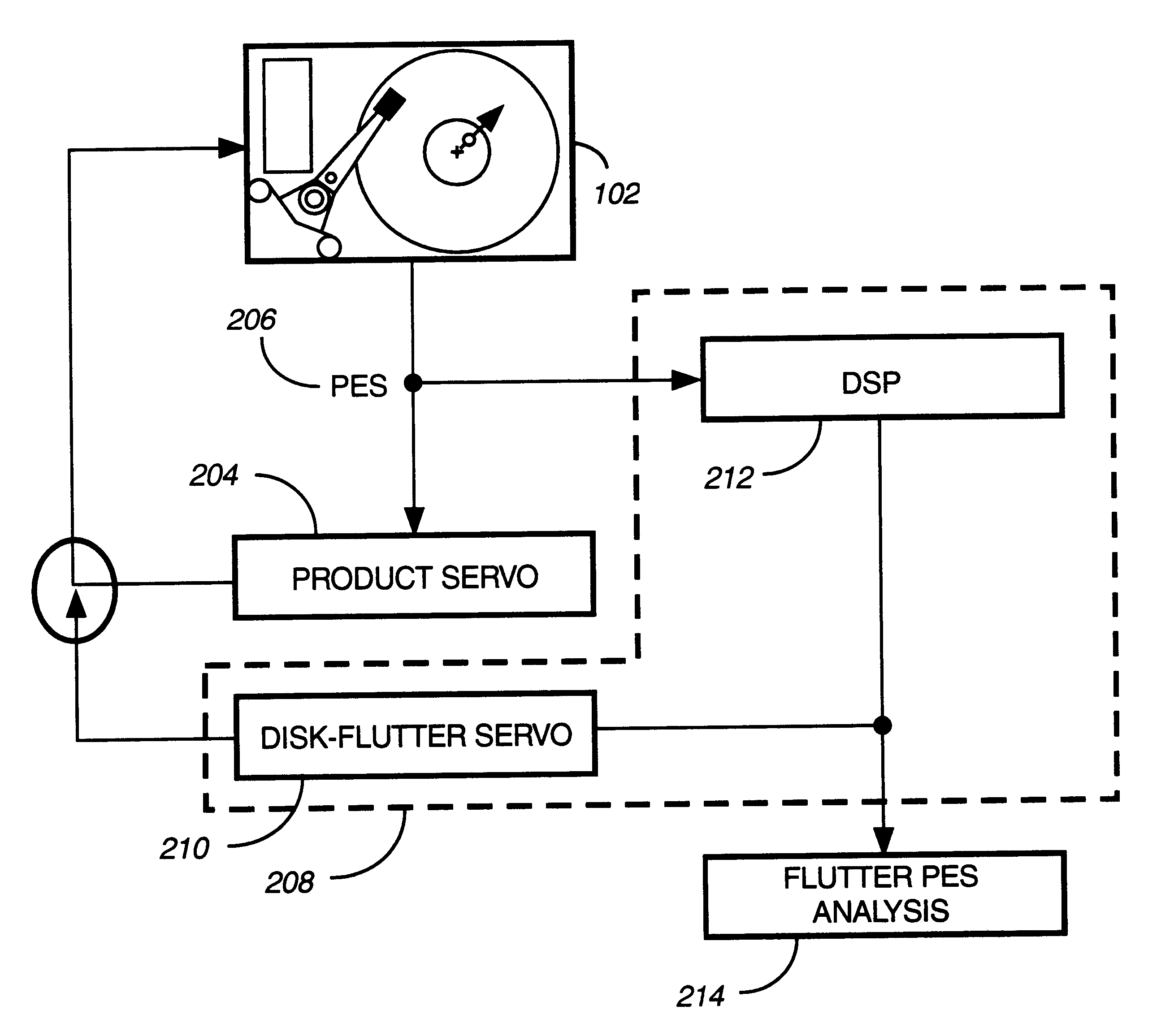
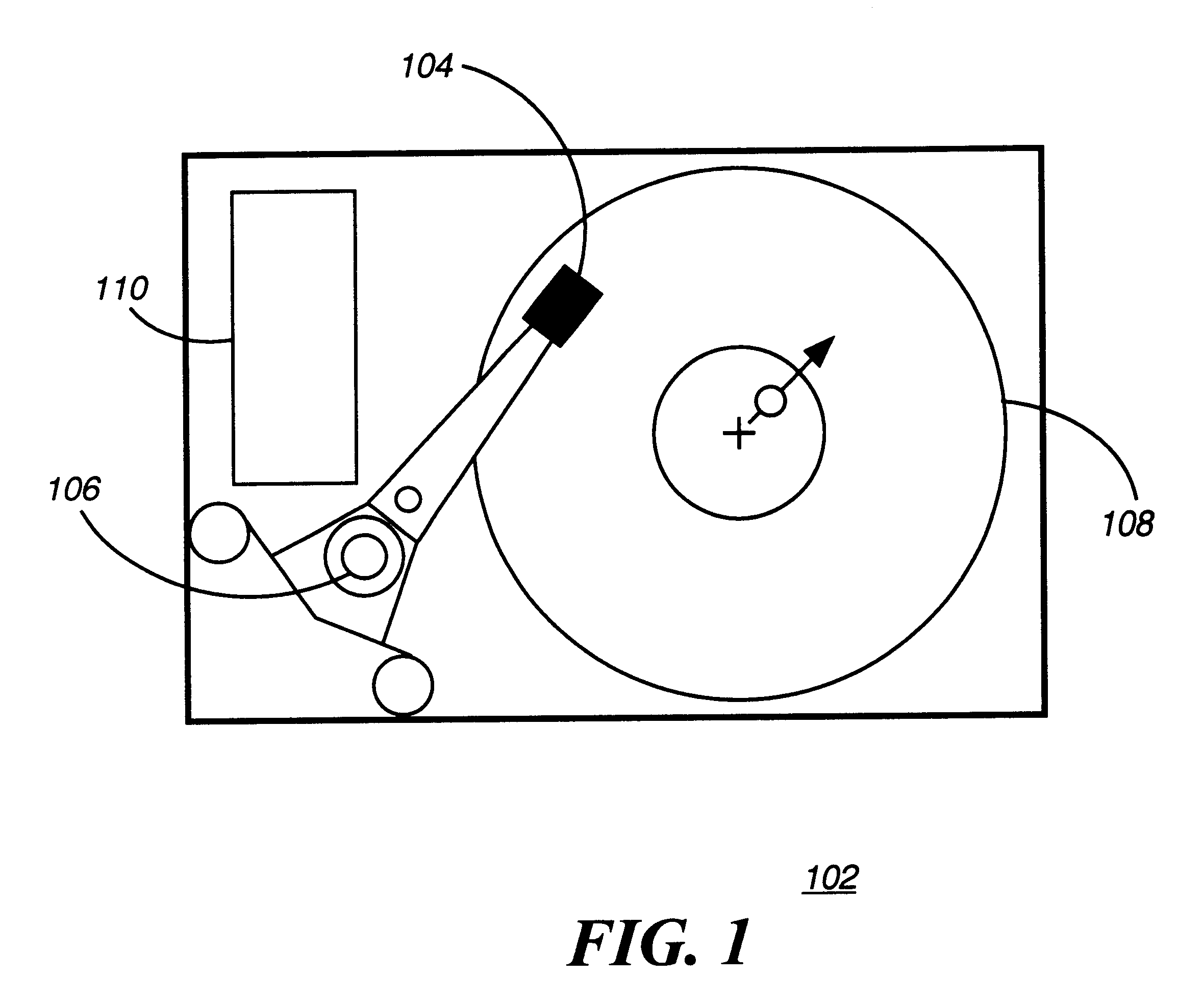
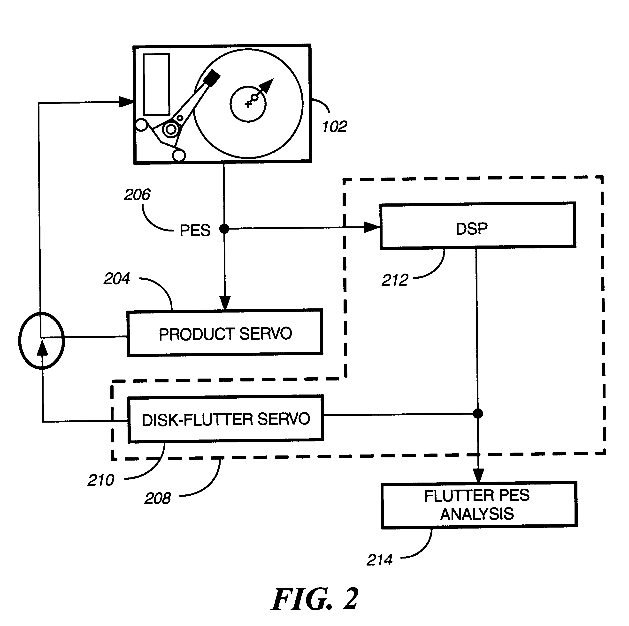
FIG. 2 is a block diagram of the disk drive in FIG. 1 with a servo system tools used to evaluate and implement the disk-flutter servo according to the present invention. The disk-flutter tool consists of two parallel independent servo loops. The first servo loop is a product servo feedback loop 204 which is typically part of the control electronics 110 for the servo actuator 202. A position error signal (PES) 206 is read from the servo actuator 202. Following servo principles known in the art, the PES 206 is used to corr...


PUM

PropertyMeasurementUnit
frequency domain plotaaaaaaaaaa
frequencyaaaaaaaaaa
frequency domain plotsaaaaaaaaaa

Abstract

In order to handle platter flutter in a hard disk operated at high speed (e.g. 10,000 RPM) and maintain tracking of read/write head, peak filters are added to a head tracking servo feedback loop. In some embodiments, several lag-lead type peak filters centered at a plurality of flutter mode frequencies are provided to process a Position Error Signal (PES) read from the read/write head. The several filter are preferably arranged in series (i.e. to operate on the PES sequentially), alternatively the filters can be arranged in parallel. Phase lags and leads caused by the several filters partially cancel at frequencies intermediate center frequencies of the several filters. According to another embodiment two or more, preferably three narrow band filters are used to cover the spectrum of each flutter mode. In a configuration mode, a spectrum of the flutter modes can be obtained and used to set the center frequencies, and bandwidths of filters used to filter out the flutter modes.

Description

Not applicable1. Field of the InventionThe invention disclosed broadly relates to data storage devices. More particularly, the present invention relates to techniques for correcting the adverse effects of vibrations on servo systems in data storage devices.2. Description of the Related ArtHard disk drives are commonly used for mass storage purposes in computers. In FIG. 1 there is shown a block diagram of the major electro-mechanical components of a disk drive 102. The disk drive 102 has a read / write transducer 104, voice coil actuator 106, recording medium or disk 108, and read / write control electronics 110. There is a constant demand for increase storage capacity and reduced disk access times as new software and new applications become available. The present generation of hard disk drives 102 are designed to operate in a portable, a desk-top and a server environment. In order to meet the demand for lower disk access times, the spindle rotation speed for disk 108 has been on the in...

Claims


Application Information

Patent Timeline
Patent Type & Authority Patents(United States)
IPC IPC(8): G11B5/596
CPCG11B5/59633
Inventor SRI-JAYANTHA, S. M.DANG, HIENSHARMA, ARUNSATOH, KIYOSHIUEDA, TETSUOOHZEKI, HIDEKIKAGAMI, NAYOUKITAKEUCHI, KIOCHI
Owner WESTERN DIGITAL TECH INC
Why Eureka
Try Eureka