Line transition device between dielectric waveguide and waveguide, and oscillator, and transmitter using the same

a technology of dielectric waveguide and waveguide, which is applied in the direction of waveguides, resonators, electrical equipment, etc., can solve the problems of lowering the transmission efficiency, high cost, and inconvenient changing of the line transition devi

Inactive Publication Date: 2002-12-03
MURATA MFG CO LTD
View PDF10 Cites 31 Cited by
  • Summary
  • Abstract
  • Description
  • Claims
  • Application Information

AI Technical Summary

Benefits of technology

This construction does not employ a construction with radiation from the end of the dielectric strip in the direction of the axis, which prevents unnecessary radiation, and which enables line transition converting to be performed with low loss. In addition, since the propagating direction of electromagnetic wave in the dielectric waveguide is perpendicular to that in the waveguide, the degree of freedom in designing a circuit construction is increased and miniaturization of the entire transition device can be achieved.
The above dielectric waveguide may be located between a pair of conductive plates facing each other. By unifying a part of the pair of conductive plates and an end of the waveguide, it is easy to obtain matching between the dielectric waveguide and the waveguide. Alternatively, in the transition device between the dielectric waveguide and the waveguide, by locally changing the shape of a cross section of the waveguide, it is easy to obtain matching between both the dielectric waveguide and the waveguide.
An oscillator of the present invention includes an oscillating element in the waveguide and a coupling conductor. The oscillating output signal is transmitted from the oscillating element and is electromagnetically coupled with the coupling conductor in a resonance mode of the waveguide. This construction allows the oscillating output signal to be converted into a signal in the transmission mode of the dielectric waveguide through the resonance mode of the waveguide. These constructions enable the oscillating signal to be easily transmitted through the dielectric waveguide.
A transmitter of the present invention includes the dielectric waveguide, an antenna device having the primary radiator employing the waveguide, and an oscillator generating a transmission signal to the antenna device. Alternatively, the transmitter includes the dielectric waveguide, the oscillator employing the waveguide, and the antenna device transmitting the output signal from the oscillator. With above these constructions, the transmitter having small size, low loss, and a broad band can be obtained.

Problems solved by technology

Moreover, such a line transition device is not suitable for changing the propagating direction of a signal because a bend at the transition causes lowering of the transmission efficiency.
This structure requires a reflector or the like to shield the through-hole, apart from a connection part between the through-hole and the dielectric waveguide, so that a signal propagating from the dielectric waveguide to the through-hole does not leak, which results in a higher cost.
However, because the dielectric resonator is used as a primary radiator, it is difficult to expand a frequency band of the antenna.

Method used


Image

  • Line transition device between dielectric waveguide and waveguide, and oscillator, and transmitter using the same
  • Line transition device between dielectric waveguide and waveguide, and oscillator, and transmitter using the same
  • Line transition device between dielectric waveguide and waveguide, and oscillator, and transmitter using the same

Examples


first embodiment

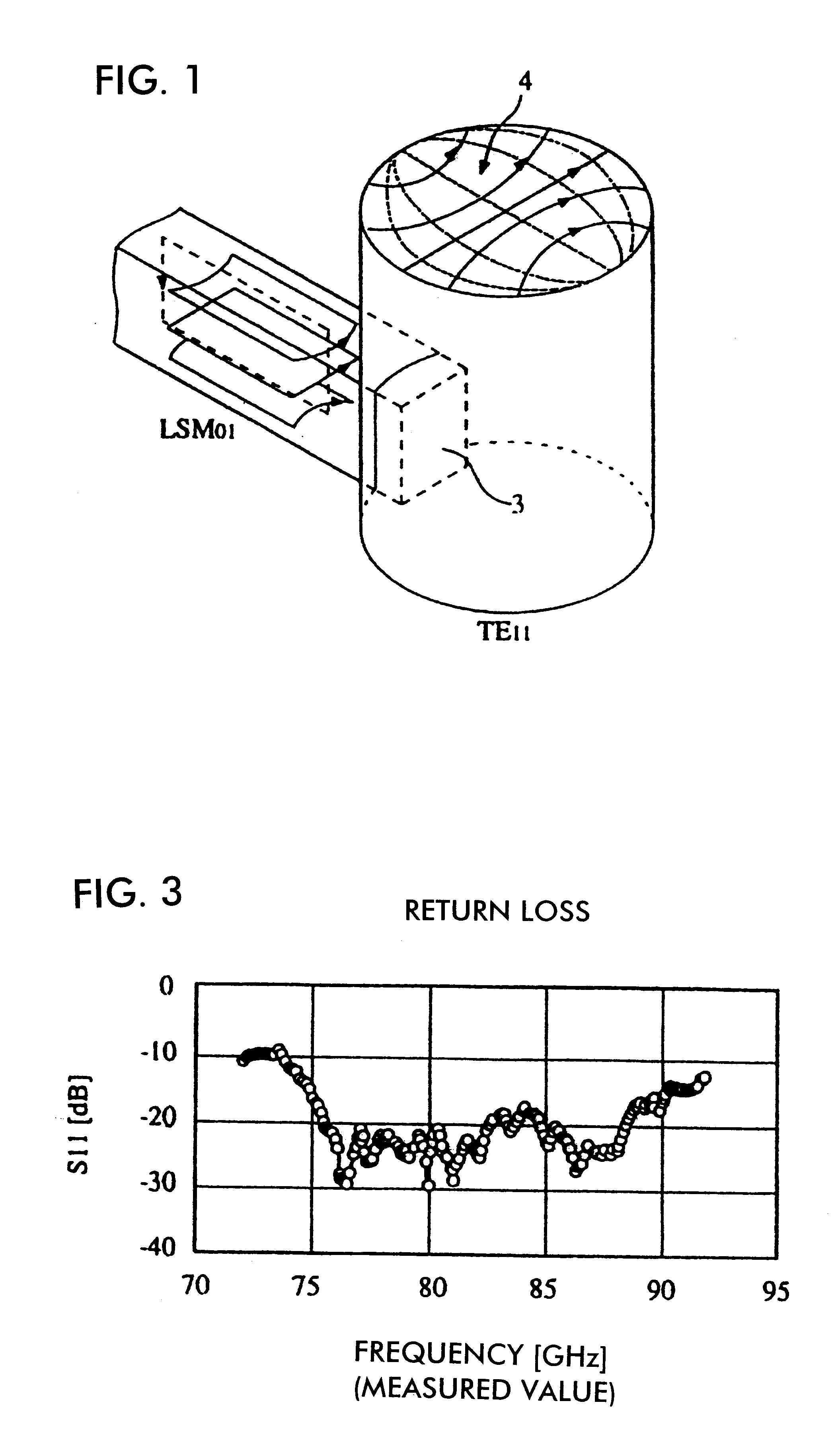
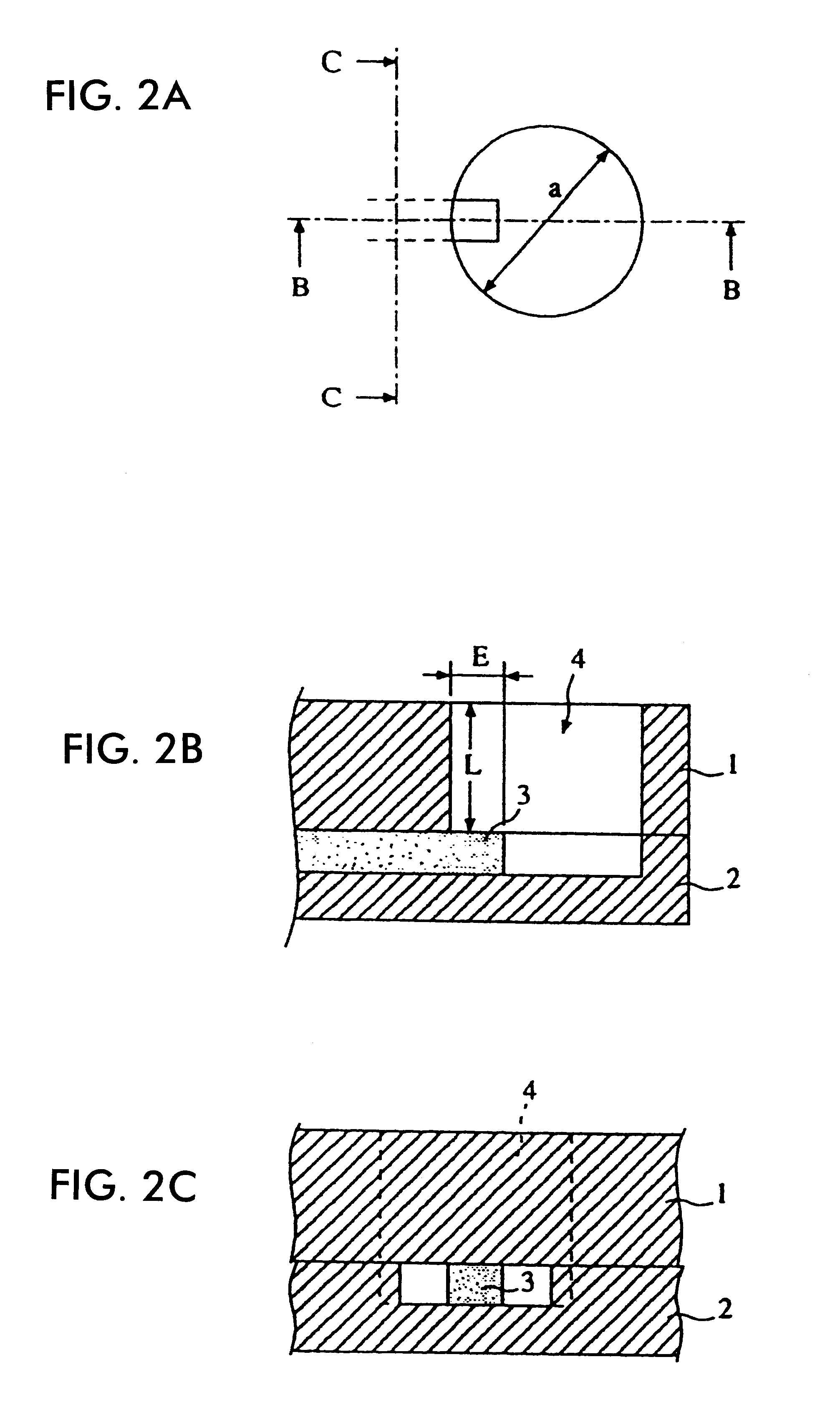
A construction of a transition device between a dielectric-waveguide and a waveguide according to the present invention is described with reference to FIGS. 1 to 3. In FIGS. 2A to 2C, conductive plates 1 and 2 are provided so as to surround a dielectric strip 3. The conductive plates 1 and 2 and the dielectric strip 3 form an NRD guide. The conductive plate 1 has a columnar hole of which the inner diameter is .phi.a and the depth is L. The conductive plate 2 has a concave part of which the inner diameter is .phi.a and the depth is the same as the height of the dielectric strip 3. When the conductive plate 1 is stacked on the conductive plate 2, the columnar cavity waveguide 4 is formed by overlapping the hole of the conductive plate 1 with the concave part of the conductive plate 2. The cross section of the waveguide is not necessarily circular; it may be angular as required.

FIG. 1 shows an engaging relationship between the cavity waveguide 4 and the dielectric strip 3 of the NRD gu...

second embodiment

Another example of a line transition device according to the present invention is described with reference to FIGS. 4A, 4B, 5A, and 5B. In FIG. 4A, a pair of projections 5 is disposed on the inner wall of the waveguide 4 above the dielectric strip 3 of the NRD guide so that the inner diameter of the waveguide 4 is narrowed in the direction of the electric field in the circular TE.sub.11 mode. The impedance of a region in which the pair of projections 5 face each other has an intermediate value between the impedance of the NRD guide and that of the waveguide 4. Accordingly, by setting the distance between the pair of the projections 5 to an appropriate value, matching between the impedance of the NRD guide and that of the waveguide 4 can be achieved.

In FIG. 4B, instead of the pair of the projections 5, a screw 6 is disposed. By adjusting the insertion depth of the screw 6, the impedance of the waveguide 4 can be changed. As long as the internal impedance of the waveguide 4 can be adj...

third embodiment

FIGS. 6A and 6B show a construction of a line transition device according to a In this embodiment, a rectangular cavity waveguide 104 is used instead of the columnar cavity waveguide 4 in the previous embodiments. It is desirable that the propagating direction of the electromagnetic wave through the waveguide 104 is perpendicular to that of the electromagnetic wave through the NRD guide. Dimensions a and b of the waveguide 104 are appropriately determined in accordance with the operating frequency. A solid line arrow indicates the electric field distribution and a broken line arrow, perpendicular to the solid line arrow, indicates the magnetic field distribution. The basic transmission mode of the NRD guide is an LSM.sub.01 mode, the same as in FIG. 1. The basic transmission mode of the rectangular waveguide 104 is a rectangular TE.sub.10 mode. Because the direction of the magnetic field in the TE.sub.10 mode corresponds to that of the extension of a dielectric strip 103 in the mag...


PUM


Abstract

A line transition device which intervenes between a non radiative dielectric waveguide and a hollow waveguide for example, includes a dielectric waveguide having a dielectric strip held by a pair of conductors which face each other, and a waveguide, wherein a part of the dielectric strip of the dielectric waveguide is adjacent to or inserted in the hollow waveguide.

Description

1. Field of the InventionThe present invention relates to high-frequency transmission-lines, and more particularly relates to a transmission-line having a line transition device between a dielectric waveguide and a waveguide. Moreover, the invention relates to a primary radiator, an oscillator, and a transmitter which use a line transition device.2. Description of the Related ArtDielectric waveguides and waveguides. have been used as transmission lines for high frequencies, such as the microwave band, and the millimeter wave band. A typical example of a dielectric waveguide is a non-radiative dielectric (NRD) waveguide. A typical example of a waveguide is a hollow tube through which microwave electromagnetic radiation can be transmitted with relatively slight attenuation. Waveguides often have a rectangular cross section, but some have a circular cross section.A line transition device between a dielectric waveguide and a waveguide is disclosed, for example, in Japanese Laid-open Pat...

Claims


Application Information

Patent Timeline
Patent Type & Authority Patents(United States)
IPC IPC(8): H01P5/08H01P7/10
CPCH01P5/087H01P7/10
Inventor KITAMORI, NOBUMASAHIGASHI, KAZUTAKATANIZAKI, TORUYAMADA, HIDEAKIYAMASHITA, SADAO
Owner MURATA MFG CO LTD
Why Eureka
Try Eureka