Heat exchanger garment

Inactive Publication Date: 2002-12-31
CAPITAL ONE NAT ASSOC AS AGENT
View PDF7 Cites 64 Cited by
  • Summary
  • Abstract
  • Description
  • Claims
  • Application Information

AI Technical Summary

Benefits of technology

A preferred heat exchanger in accordance with the invention is such wherein each of the internal and the external layers is constructed of two layers; namely the garment is a four-layered structure. This four-layered structure consists of two impermeble sheets lining said space overlaid by usually heavier reinforcing layers. All four layers are typically made of a heat-weldable material and are point welded to one another. The two innermost layers serve to define the fluid-tight space, while the outer layers reinforce the structure and allow the application of an increased internal fluid pressure, at times up to about 3 Atm without rupturing. Increase pressure may at times be of importance to ensure a certain level of flow of the heat-control fluid within the garment's inner space. The inner layers of the heat exchange may be made of a polyethylene-based material such as Metallocene (manufactured by Dow Chemicals) sheeting, typically but not restricted to about 20-50 .mu.m thickness. The two outer layers are preferably somewhat hydrophilic to al

Problems solved by technology

Furthermore, under general anesthesia, the natural physiological mechanisms which operate to maintain a body temperature may fail, and the problem becomes particularly acute in cases where exposed internal body organs come into contact with the ambient air which results in excessive heat loss.
The problem is further aggravated

Method used


Image

  • Heat exchanger garment
  • Heat exchanger garment
  • Heat exchanger garment

Examples


Embodiment Construction

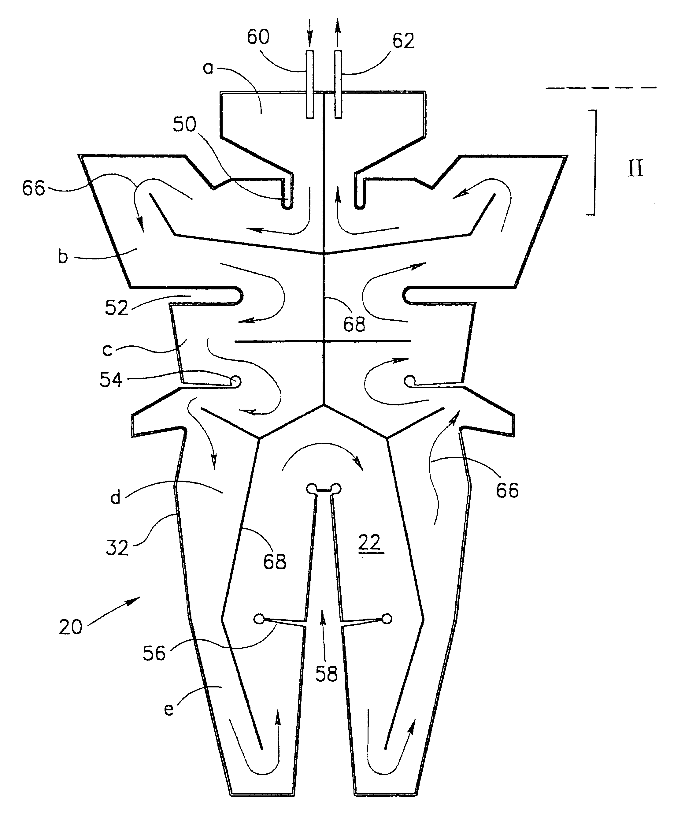
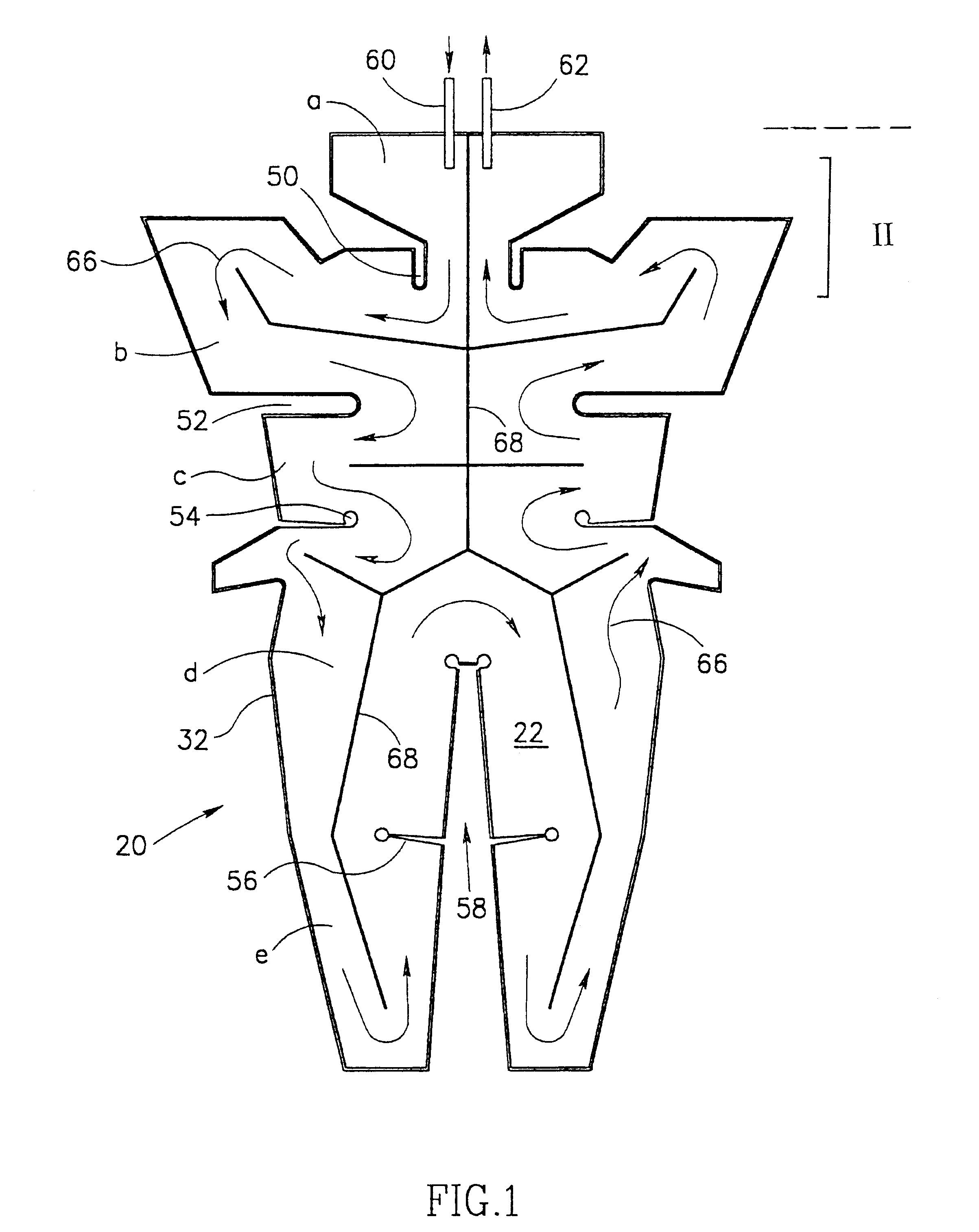
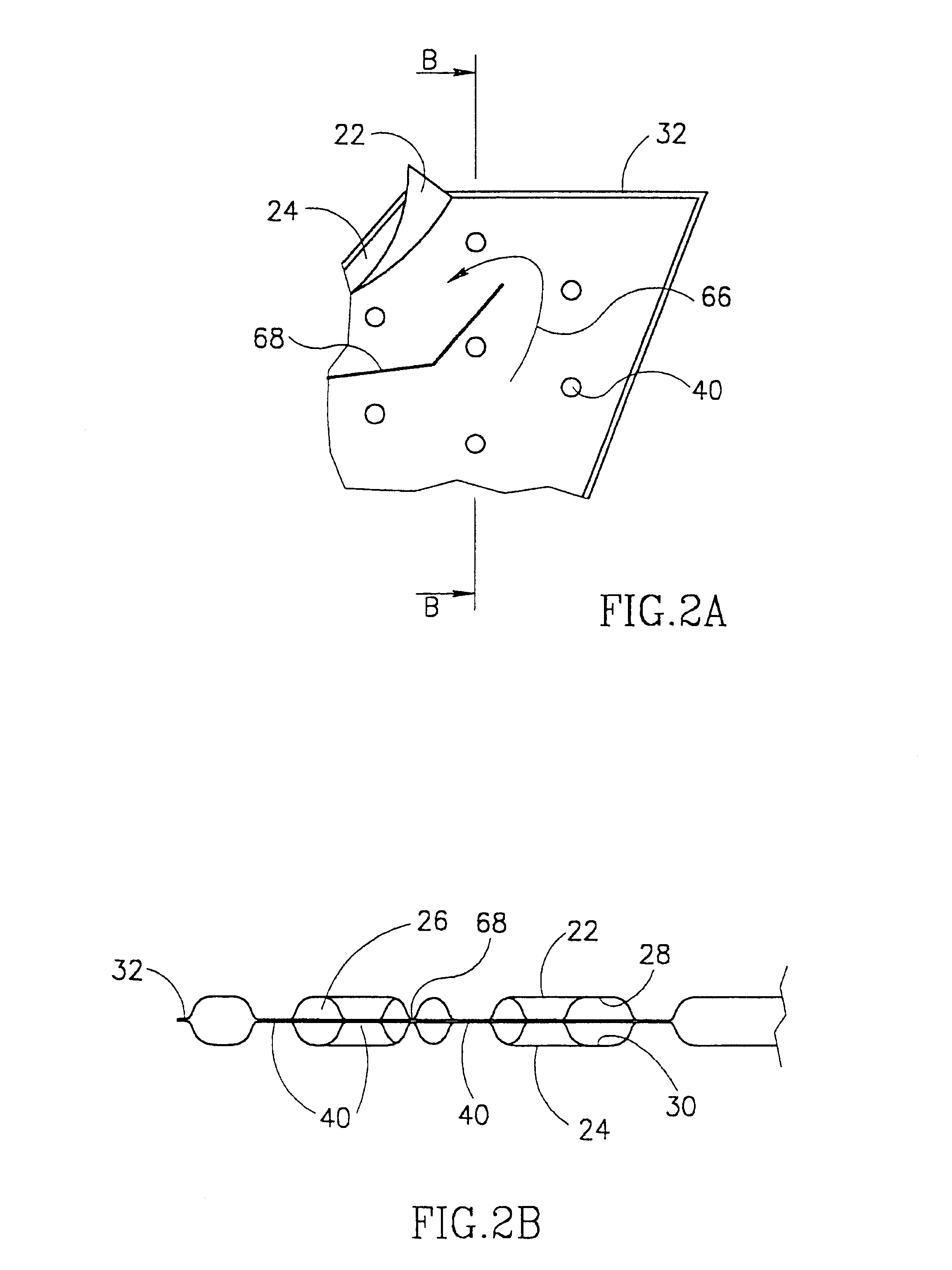
Reference is first being made to FIG. 1 showing a planar view of a garment generally designated 20 of which a part marked "II" in FIG. 1 is shown in a more enlarged view in FIG. 2A and of which a cross-section through lines B--B of FIG. 2A is shown in FIG. 2B. As can be seen in FIGS. 2A and 2B, the garment has an internal, body-facing layer 22 and an external layer 24 which define between them a fluid-tight space 26. Each of the layers 22, 24 is made from a thermoplastic material with a heat weldable, space-lining face 28, 30 (see FIG. 2B). The two layers are welded to one another in fluid tight manner at the edges 32.

The two layers 22, 24 are welded to one another at a plurality of weld points 40 seen in FIGS. 2A and 2B.

The weld points 40 cause a flow disturbance and consequently the flow of liquid through the garment (see description below) becomes uniform throughout the entire space of the flow path (see below).

The garment is symmetrical along a longitudinal midline which is a ty...


PUM


Abstract

A heat exchanger for use in controlling subject's body temperature during a medical procedure comprises a flexible garment adapted for enveloping portions of the subject's body surface with dedicated sections for enveloping different body parts. Defined within the garment is a continuous, fluid tight space, wherein a flow path for heat-control fluid is defined between fluid inlet and fluid outlet. The inner faces of the garment's internal and external layers are made of a heat-weldable material and are point-welded to one another at a plurality of locations throughout the garment with a distance between two adjacent points being between about 8 to about 20 mm.

Description

The present invention relates to a heat exchanger which is intended to be applied onto a subject's body for controlling the subject's body temperature during medical procedure.BACKGROUND OF THE INVENTION AND PRIOR ARTThere are a variety of medical procedures in which a subject's body temperature has to be controlled. For example, during open heart surgery, the body temperature has to be controllably reduced to about 35.degree. C. and then at the end of the operation increased back to normal body temperature. Furthermore, under general anesthesia, the natural physiological mechanisms which operate to maintain a body temperature may fail, and the problem becomes particularly acute in cases where exposed internal body organs come into contact with the ambient air which results in excessive heat loss. The problem is further aggravated by the fact that operation rooms are very often heavily cooled. Following surgical procedure, it may take some time until the body acquires back its abili...

Claims


Application Information

Patent Timeline
IPC IPC(8): A61F7/00A61F2/00A61F7/02
CPCA61F7/02A61F2007/0001A61F2007/0054A61F2007/0288
Inventor KUSHNIR, IGAL
Owner CAPITAL ONE NAT ASSOC AS AGENT
Why Eureka
Try Eureka