
Adjustable safety utility knife with slip resistant elements

Inactive Publication Date: 2003-01-07
JPJ INVESTMENT HLDG +1
View PDF17 Cites 37 Cited by
  • Summary
  • Abstract
  • Description
  • Claims
  • Application Information

AI Technical Summary

Benefits of technology

It is another object of the present invention to provide an adjustable safety utility knife which is simple in construction and economical to manufacture.
It is still another object of the present invention to provide a safety utility knife as in the previous objects which enhances the frictional grip to a user of the utility knife housing to counteract the pulling forces on the blade during cutting.
It is yet another object of the present invention to provide an adjustable safety utility knife as in the present invention which is comfortable to the user, substantially independently of the tightness of the grip by the user on the handle on the knife.
It is a further object of the present invention to provide an adjustable safety utility knife which is safe and convenient to use and minimizes the probability that the utility knife will be inadvertently or accidentally pulled out of the user's hand when cutting thick or heavy objects.
It is still a further object of the present invention to provide an adjustable safety utility knife which provides the user added control over the knife during use, particularly during cutting of thick or heavy objects, thereby minimizing the probability of damage to the material being cut.
In order to achieve the above objects, and others which will become apparent hereinafter, an adjustable safety utility knife in accordance with the present invention comprises an elongated ergonomically shaped handle formed of two elongate shell members, each having a peripheral edge and an outer convex surface and an inner generally concave surface. Fastening means is provided for fastening such shell members at said peripheral edges along a vertical parting plane to form an elongated internal cavity. Said handle defines a front end, a back end and an intermediate portion suitable for being gripped by a user and also defining top and bottom surfaces extending along opposite sides of said front end substantially aligned with said parting plane and dimensioned for passage of a flat cutting blade therethrough. Guide means is provided within said elongated cavity for guiding the cutting blade between a first position for safely storing the blade fully inside said cavity and a second position for selectively extending the blade beyond said aperture to expose at least a portion thereof A manually operated button is arranged on said top surface and coupled to said guide means for selectively moving the blade between said first and second positions. Slip resistant means is provided secured to said shell along said top and bottom surfaces between a rearmost operative position of said manually operated button and said back end. Such slip resistant means generally conforms to said outer convex surface and enhances gripping of said handle and minimizes slippage of said handle during use of the utility knife when gripped by a user.

Problems solved by technology

While the flat cutting blades used in utility knives are relatively thin, substantial frictional forces are frequently applied to or exerted on these blades, such as when the blades are used to cut heavy or thick cardboard, wallboard or the like.
Known utility knives, however, are typically made of metallic housings which provide a limited amount of friction between the exterior surface of the housing and the user's hand.
While such textured surfaces have somewhat increased the ability of the user to grip the utility knife housing, the greater the surface irregularities to enhance the gripping action, the more uncomfortable the knife is to use as any such surface irregularities tend to penetrate the skin of the user when the knife is tightly gripped to overcome the pulling frictional forces on the blade.

Method used


Image

  • Adjustable safety utility knife with slip resistant elements
  • Adjustable safety utility knife with slip resistant elements
  • Adjustable safety utility knife with slip resistant elements

Examples


Embodiment Construction

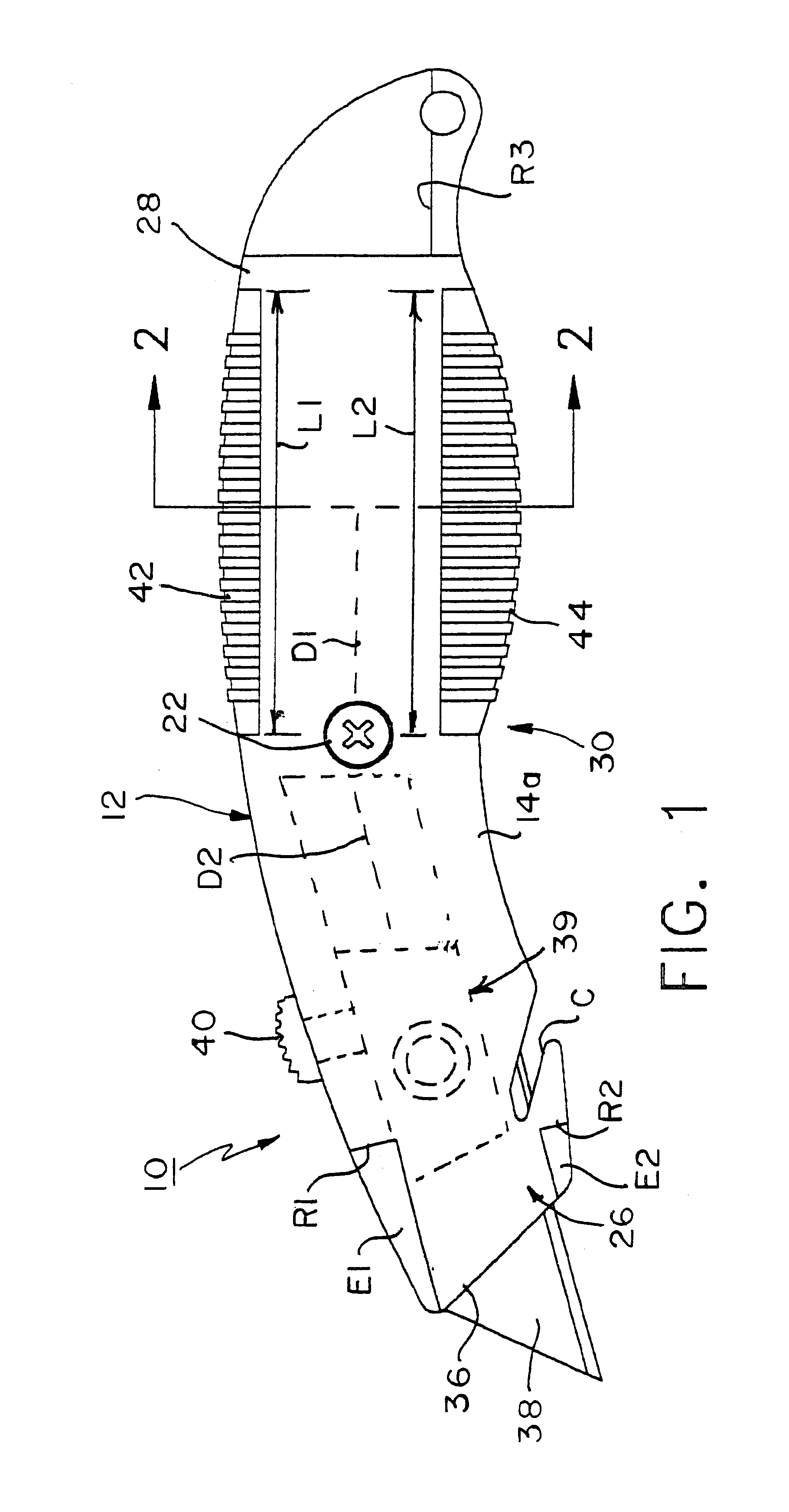
Referring now to the Figs., in which identical or similar parts will be designated by the same reference numerals throughout, and first referring to FIG. 1, an adjustable safety utility knife in accordance with the present invention is generally designated by the reference numeral 10.

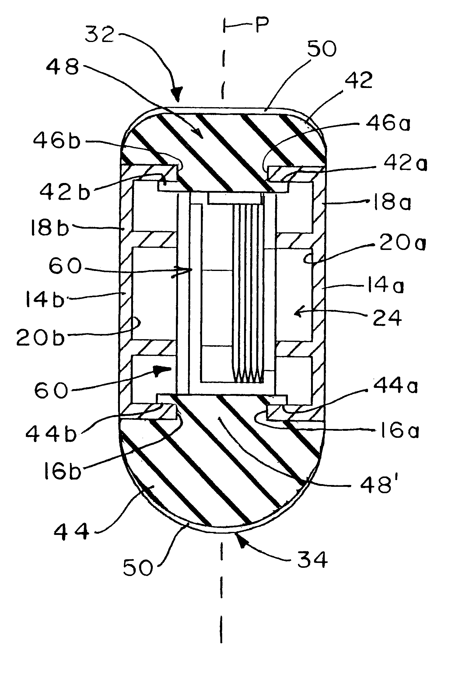
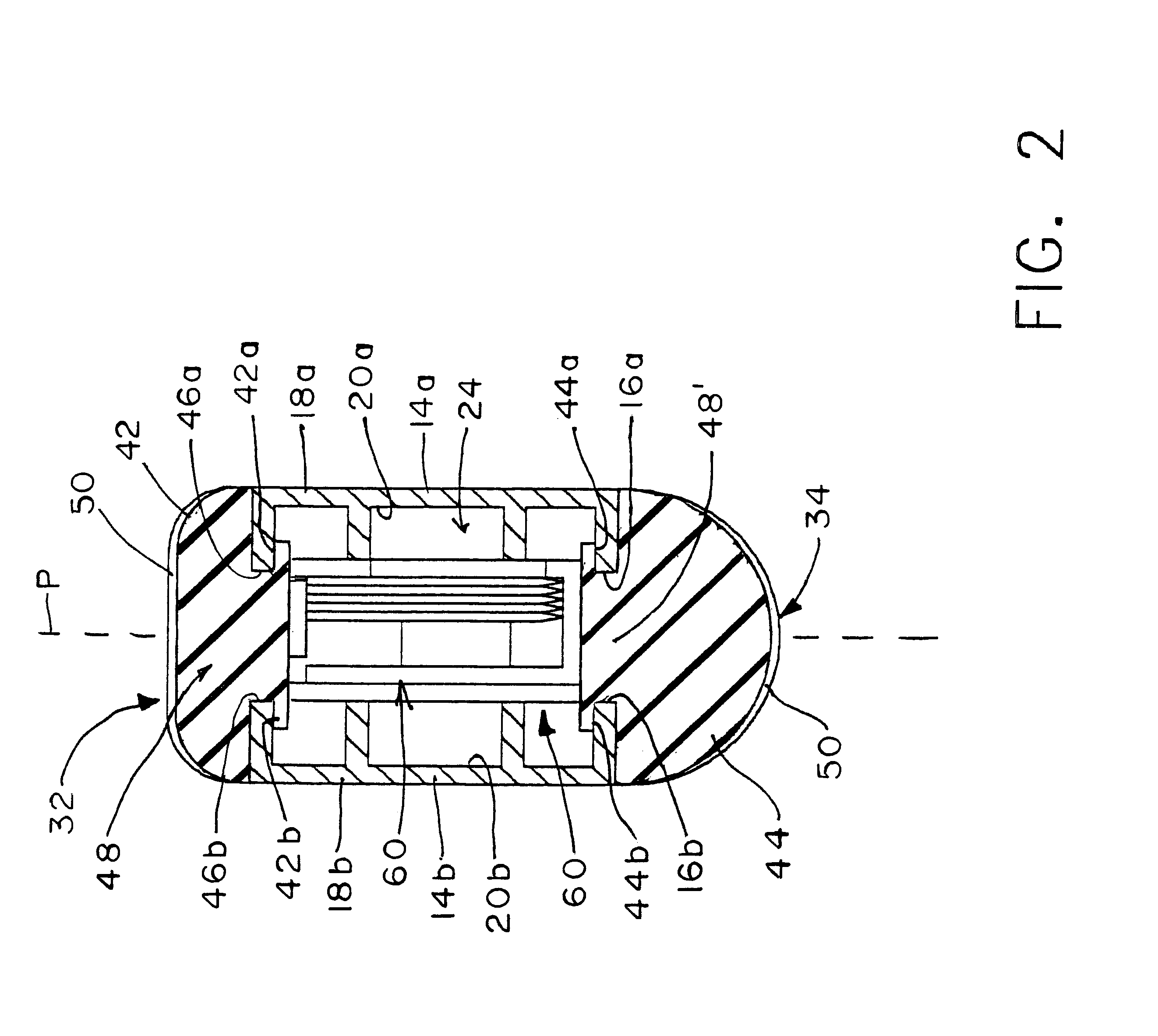
The utility knife 10 includes an elongated ergonomically shaped handle 12 formed of two elongate shell members 14a, 14b, each having a peripheral edge 16a, 16b (FIG. 2), respectively, and outer, generally convex surface 18a, 18b and an inner generally concave surface 20a, 20b, respectively. A suitable fastener, such as a transverse screw 22 (FIG. 1) is provided for fastening the shell members 14a, 14b to each other at the peripheral edges 16a, 16b along a parting plane P (FIG. 2) to form an elongated internal cavity or compartment 24. The handle 12 defines a front end 26, a back end 28 and an intermediate portion 30 suitable to be gripped by the user, also defining top and bottom surfaces 32, 34, respec...


PUM


Abstract

An adjustable safety utility knife includes a elongated ergonomically shaped handle formed of two elongate shell members each having a peripheral edge and an outer, generally convex surface and an inner generally concave surface. A fastener secures the shell members together at their peripheral edges along a parting plane to form an elongated internal cavity. The handle defines a front end, back end and an intermediate portion suitable for being gripped by a user and also defines top and bottom surfaces extending along opposite sides of the shell members along the peripheral edges. The handle has a slot-like aperture at the front end substantially aligned with the parting plane and dimensioned for passage of a flat cutting blade therethrough. The cutting blade is mounted for movement by a suitable guide member or a carriage between a first position for safely storing the blade fully inside the cavity and a second position for selectively extending the blade beyond the aperture to expose at least a portion thereof. A manually operated button is arranged on the top surface of the handle and is coupled to guide element or blade carriage for selectively moving the blade between the first and second positions. Slip resistant elements are secured to the shell members along the top and bottom surface between a rearwardmost operative position of the manually operated button and the back end of the handle. The slip resistant elements generally conform to the outer convex surface of the handle and enhance gripping of the handle and minimize slippage thereof during use of the utility knife when gripped by a user.

Description

1. Field of the InventionThe present invention generally relates to hand tools and, more specifically, to an adjustable safety utility knife with slip resistant elements.2. Description of the Prior ArtUtility knives are widely used in construction, business and hobby applications for cutting such materials as paperboard, wallboard, tiles, string and other objects. Typically, such utility knives are in the form of an elongate hollow housing that can be gripped by the user along an intermediate portion thereof and into which there are placed trapezoidal flat cutting blades. The blades typically have a single cutting edge. The blade is typically slidably mounted on a carrier for movement between a retracted position within the housing and an extended position in which the cutting edge is at least partially exposed through a front end aperture or slot, the carrier being coupled to a manually operated element, such as a button positioned in a manner convenient to be actuated by the user'...

Claims


Application Information

Patent Timeline
IPC IPC(8): B26B5/00
CPCB26B5/001
Inventor KHACHATOORIAN, ZAREHQIU, JIAN PING
Owner JPJ INVESTMENT HLDG
Learn More